GM Service Manual Online
For 1990-2009 cars only
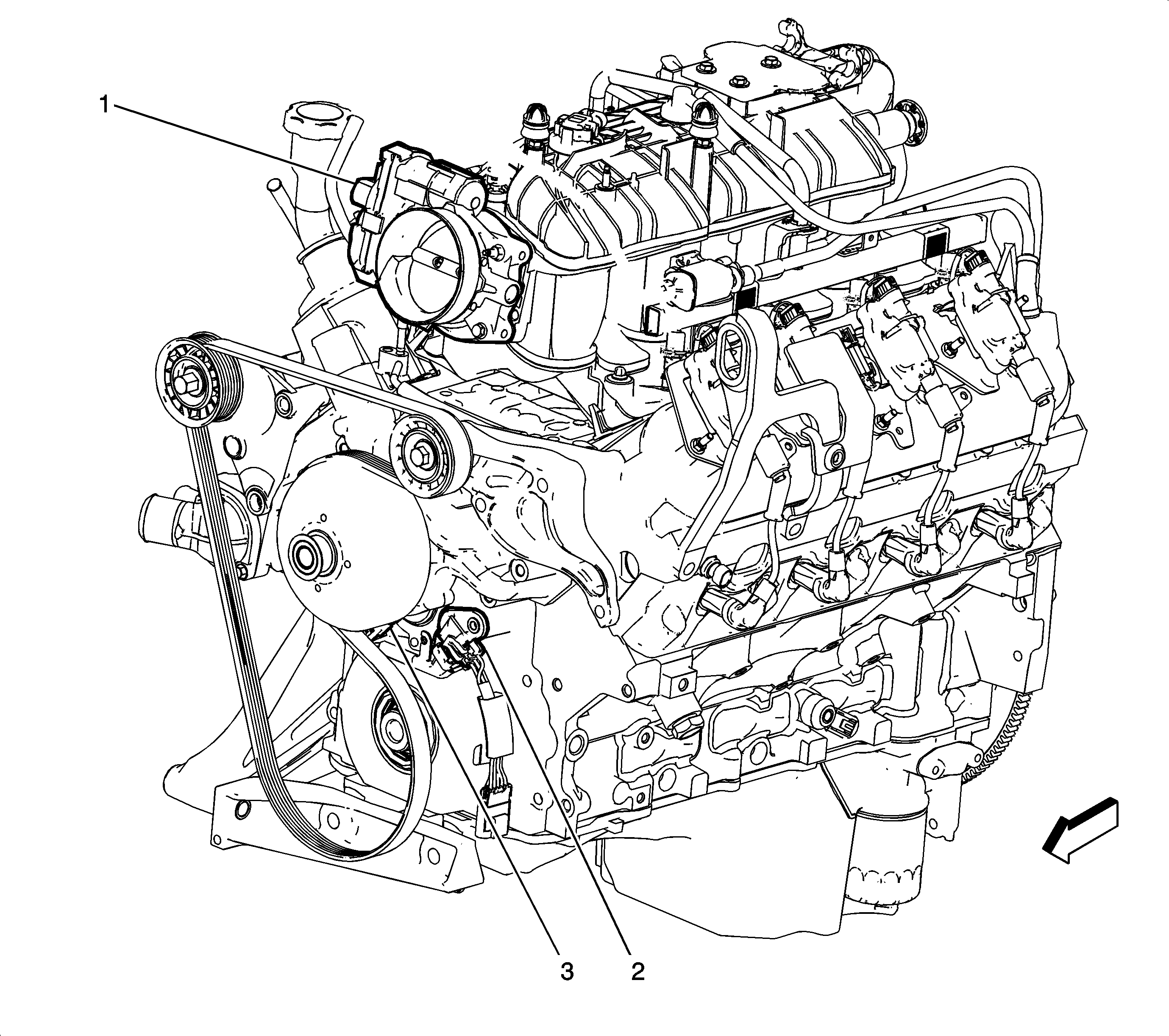
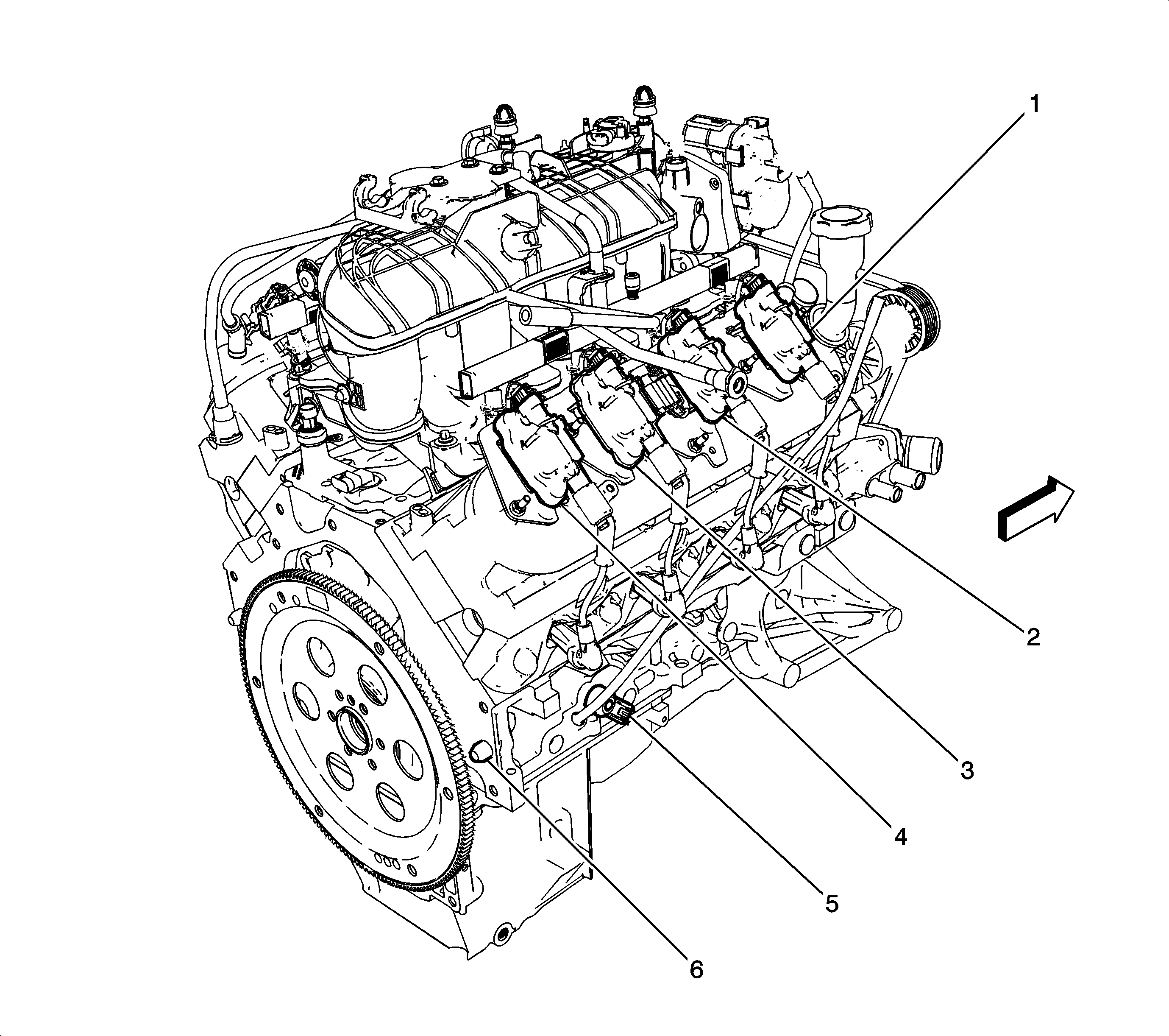
Figure 1:

Left Front Side of the Engine Components

Object Number: 1714191  Size: LF
(1)Throttle Body
(2)Manifold Absolute Pressure (MAP) Sensor
(3)Evaporative Emission (EVAP) Canister Purge Solenoid Valve
(4)Knock Sensor (KS) 1
(5)Engine Block Heater
(6)Engine Coolant Temperature (ECT) Sensor
(7)Camshaft Position (CMP) Sensor
(8)Generator (except HP2)
Figure 2:

Engine - Front View (HP2)


Object Number: 1985478  Size: LF
(1)Throttle Body
(2)Camshaft Position (CMP) Sensor
(3)Camshaft Position (CMP) Sensor Magnet
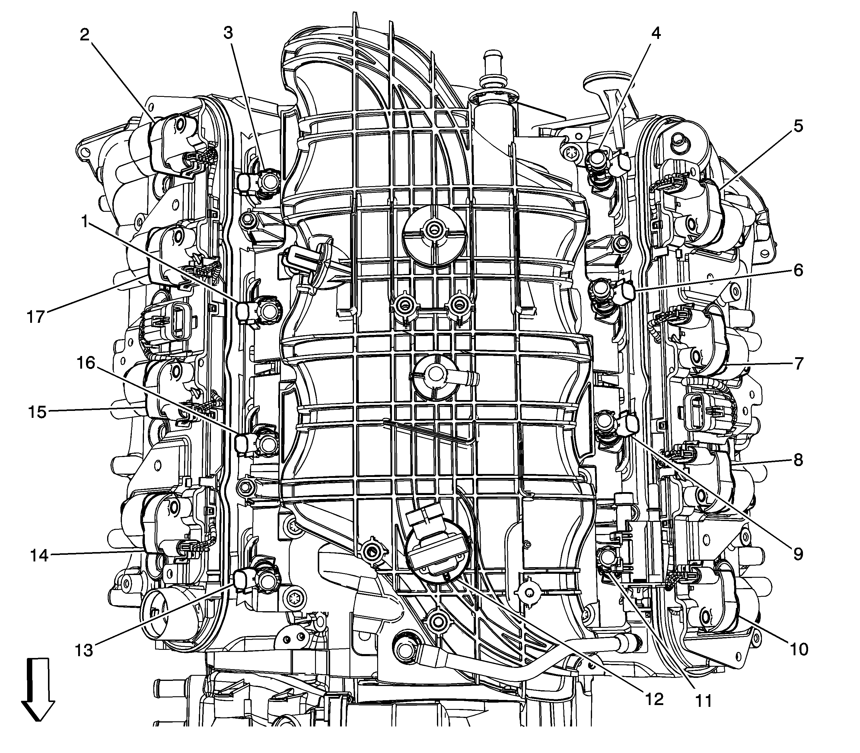
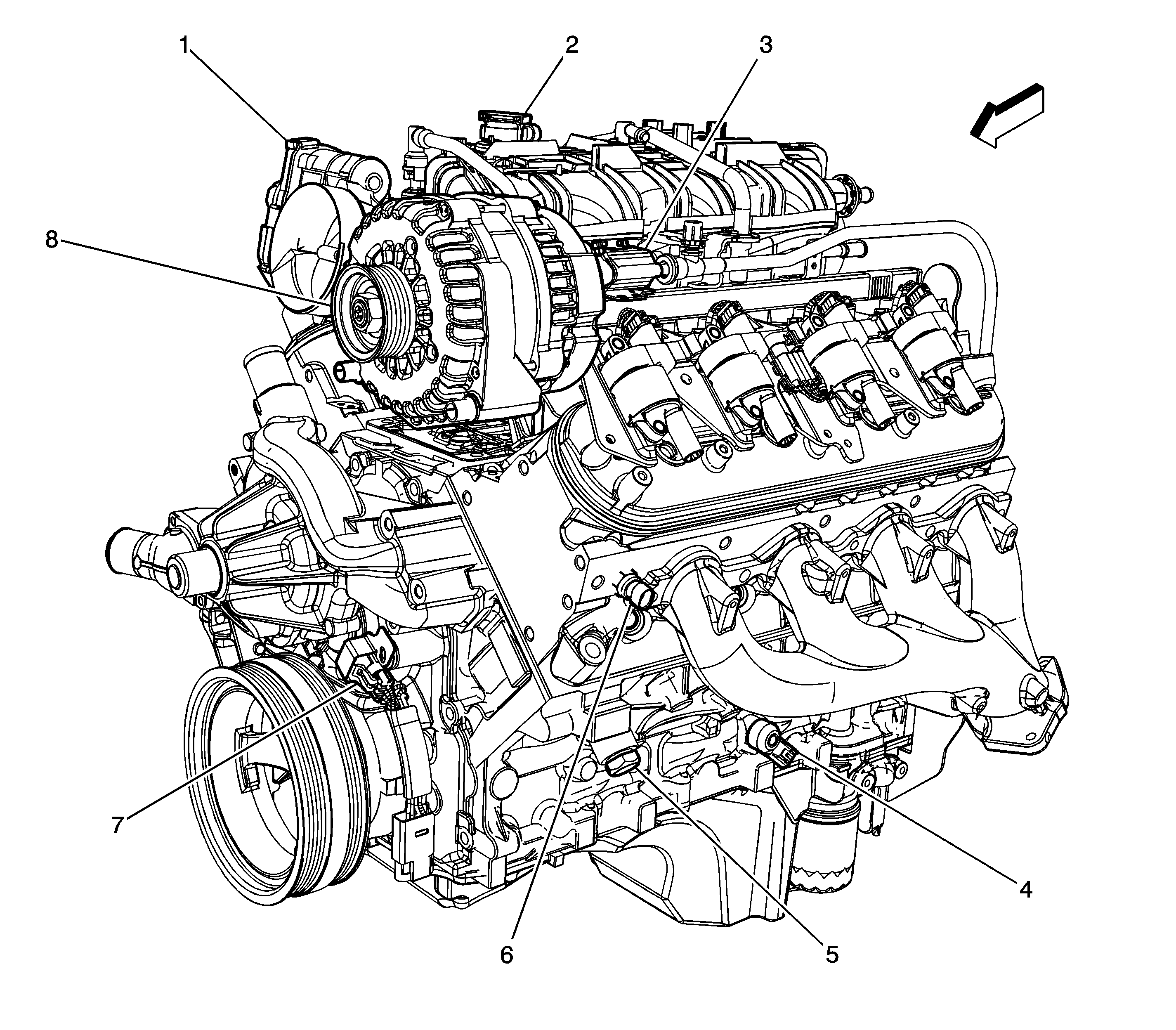
Figure 3:

Top of the Engine Components


Object Number: 1714214  Size: LF
(1)Fuel Injector 6
(2)Ignition Coil 8
(3)Fuel Injector 8
(4)Fuel Injector 7
(5)Ignition Coil 7
(6)Fuel Injector 5
(7)Ignition Coil 5
(8)Ignition Coil 3
(9)Fuel Injector 3
(10)Ignition Coil 1
(11)Fuel Injector 1
(12)Manifold Absolute Pressure (MAP) Sensor
(13)Fuel Injector 2
(14)Ignition Coil 2
(15)Ignition Coil 4
(16)Fuel Injector 4
(17)Ignition Coil 6
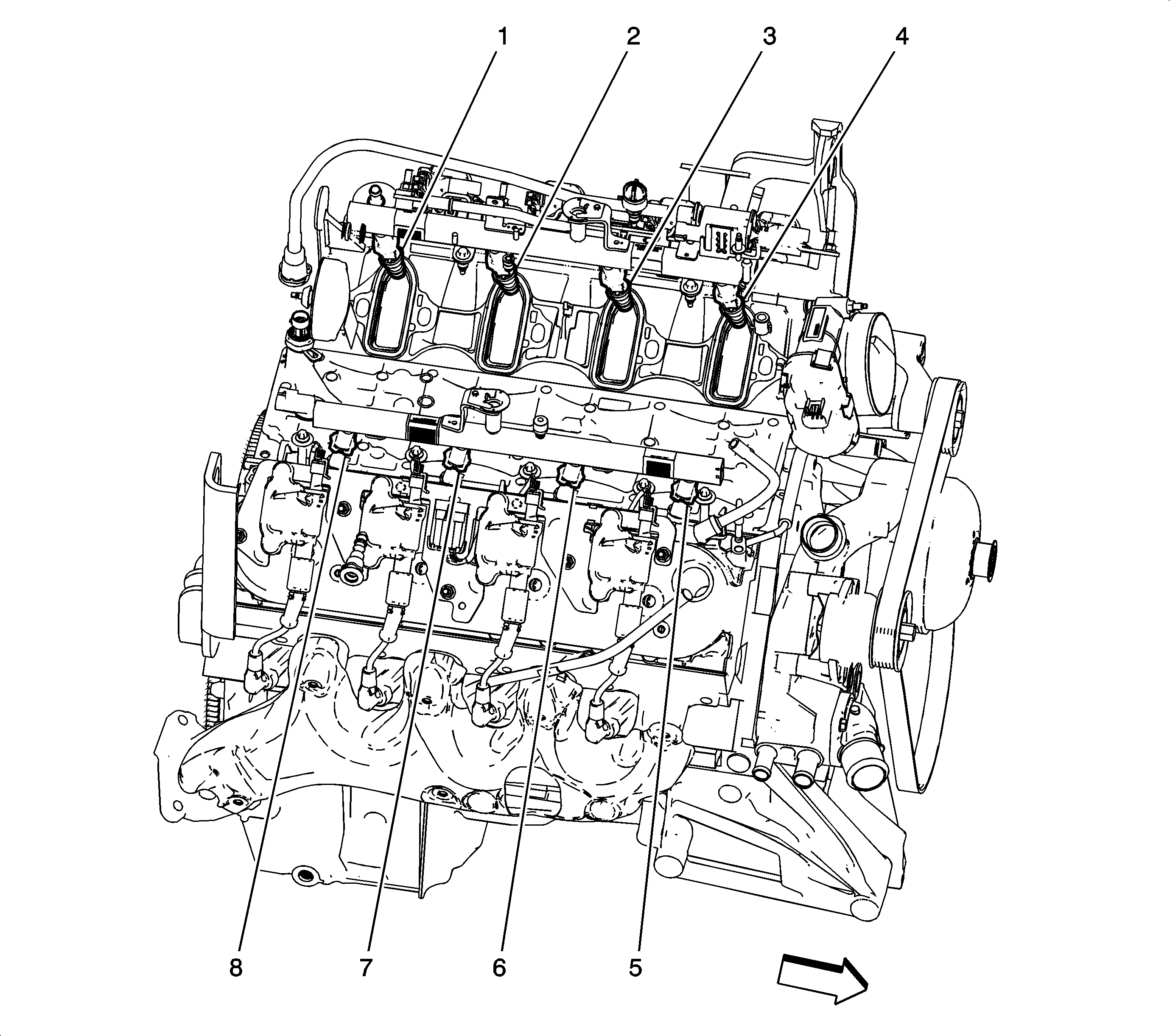
Figure 4:

Engine - Top View (HP2)


Object Number: 1985455  Size: LF
(1)Fuel Injector 7
(2)Fuel Injector 5
(3)Fuel Injector 3
(4)Fuel Injector 1
(5)Fuel Injector 2
(6)Fuel Injector 4
(7)Fuel Injector 6
(8)Fuel Injector 8
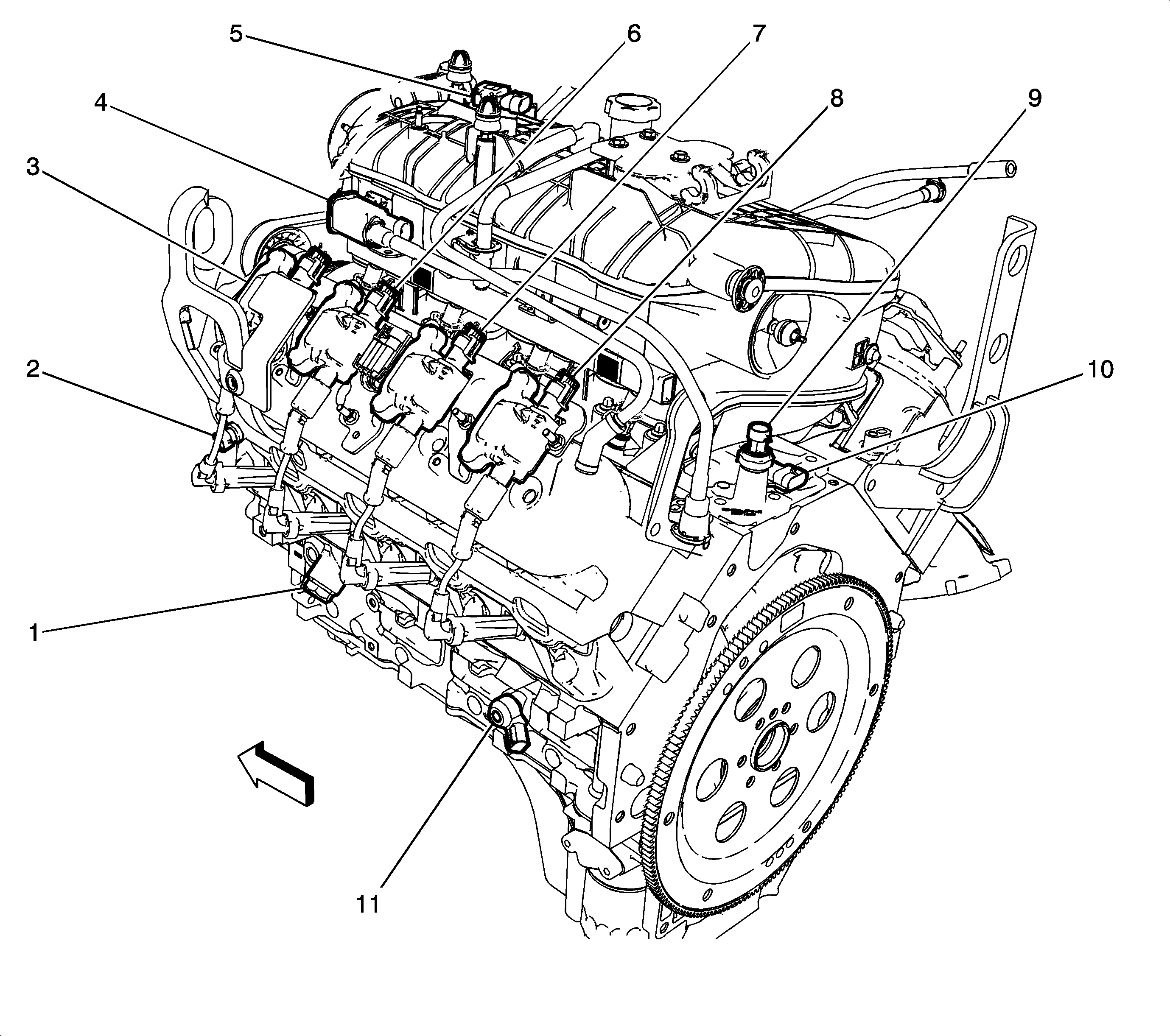
Figure 5:

Right Rear Side of the Engine Components
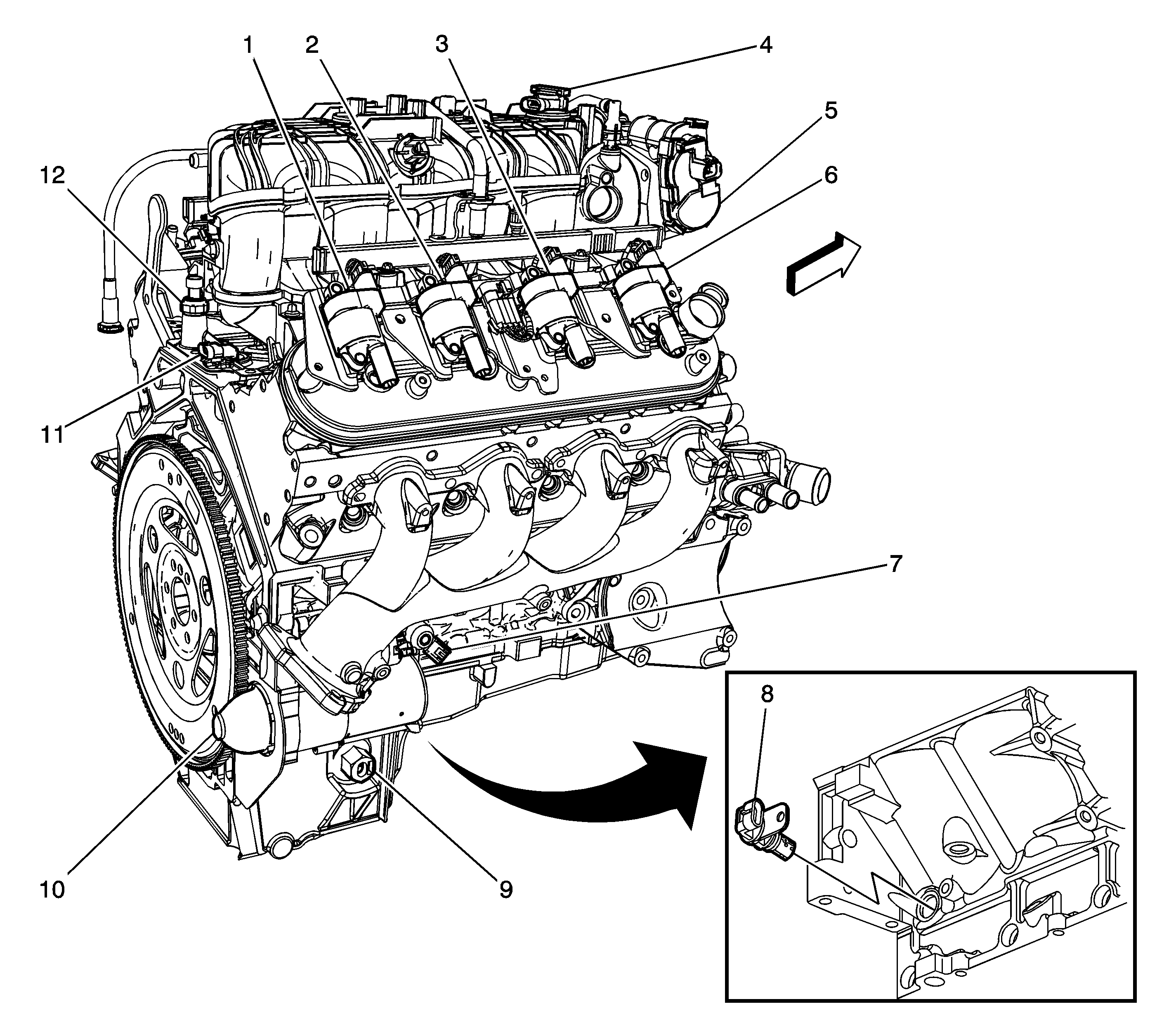

Object Number: 1714216  Size: LF
(1)Ignition Coil 8
(2)Ignition Coil 6
(3)Ignition Coil 4
(4)Manifold Absolute Pressure (MAP) Sensor
(5)Throttle Body
(6)Ignition Coil 2
(7)Knock Sensor (KS) 2
(8)Crankshaft Position (CKP) Sensor
(9)Engine Oil Level (EOL) Switch (Early Production)
(10)Starter Motor (except HP2)
(11)Valve Lifter Oil Manifold (VLOM) Assembly (LY5, LMG, L76 or LC9)
(12)Engine Oil Pressure (EOP) Sensor
Figure 6:

Engine - Left Rear (HP2)


Object Number: 1985458  Size: LF
(1)Engine Block Heater Connector
(2)Engine Coolant Temperature (ECT) Sensor
(3)Ignition Coil 1
(4)Evaporative Emissions (EVAP) Canister Purge Solenoid Valve
(5)Manifold Absolute Pressure (MAP) Sensor
(6)Ignition Coil 3
(7)Ignition Coil 5
(8)Ignition Coil 7
(9)Engine Oil Pressure (EOP) Sensor
(10)Valve Lifter Oil Manifold (VLOM) Assembly (DOD)
(11)Knock Sensor (KS) 1
Figure 7:

Engine - Right Rear (HP2)


Object Number: 1985471  Size: LF
(1)Ignition Coil 2
(2)Ignition Coil 8
(3)Ignition Coil 6
(4)Ignition Coil 4
(5)Knock Sensor (KS) 2
(6)Crankshaft Position (CKP) Sensor
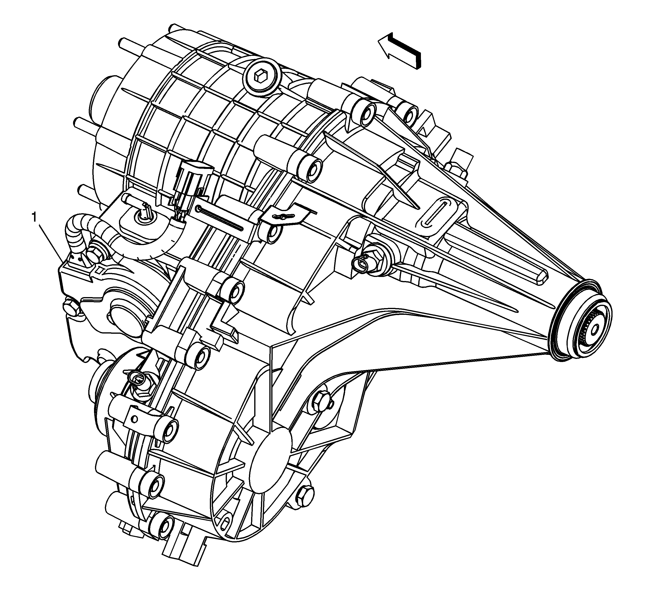
Figure 8:

Transfer Case Components NQH


Object Number: 1836101  Size: LF
(1)Transfer Case Encoder Motor
Figure 9:

Left Side of the Transmission Components (M30 or M70)
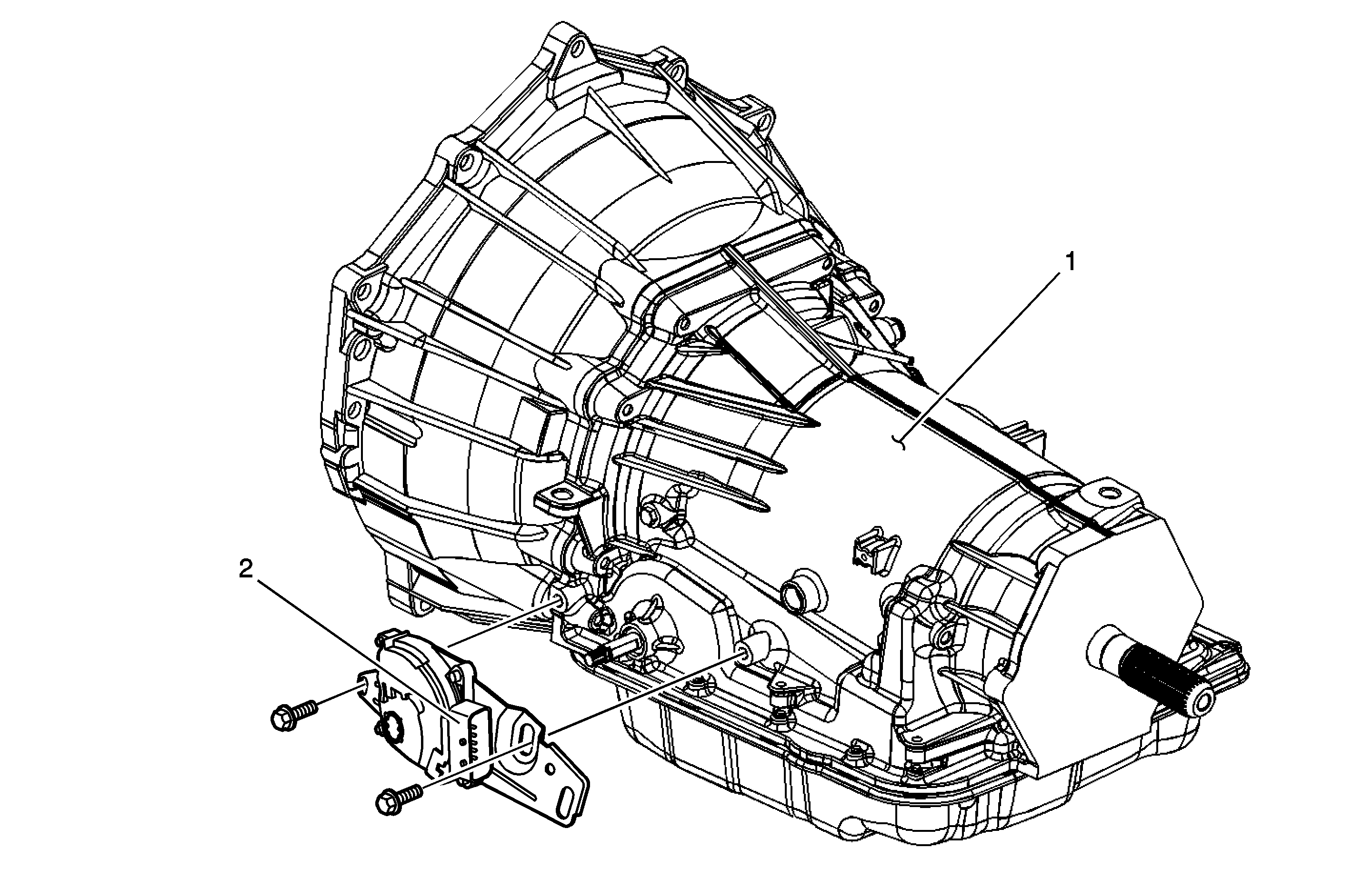

Object Number: 1283232  Size: MF
(1)Automatic Transmission
(2)Park/Neutral Position (PNP) Switch
Figure 10:

Transmission/Transfer Case Components (HP2)
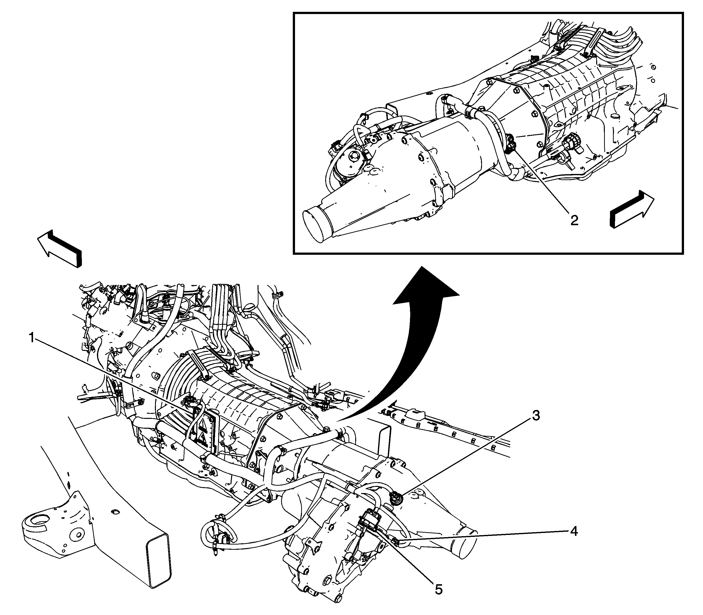

Object Number: 1985295  Size: LF
(1)Transmission Power Inverter Module (3 Phase) Cable Cover
(2)Vehicle Speed Sensor (VSS) - 2WD
(3)Vehicle Speed Sensor (VSS) - 4WD
(4)Transfer Case 2/4 Wheel Drive Actuator Position Sensor (NQH)
(5)Transfer Case Encoder Motor (NQH)
Figure 11:

Inside the Transmission Components (M30 or M70)
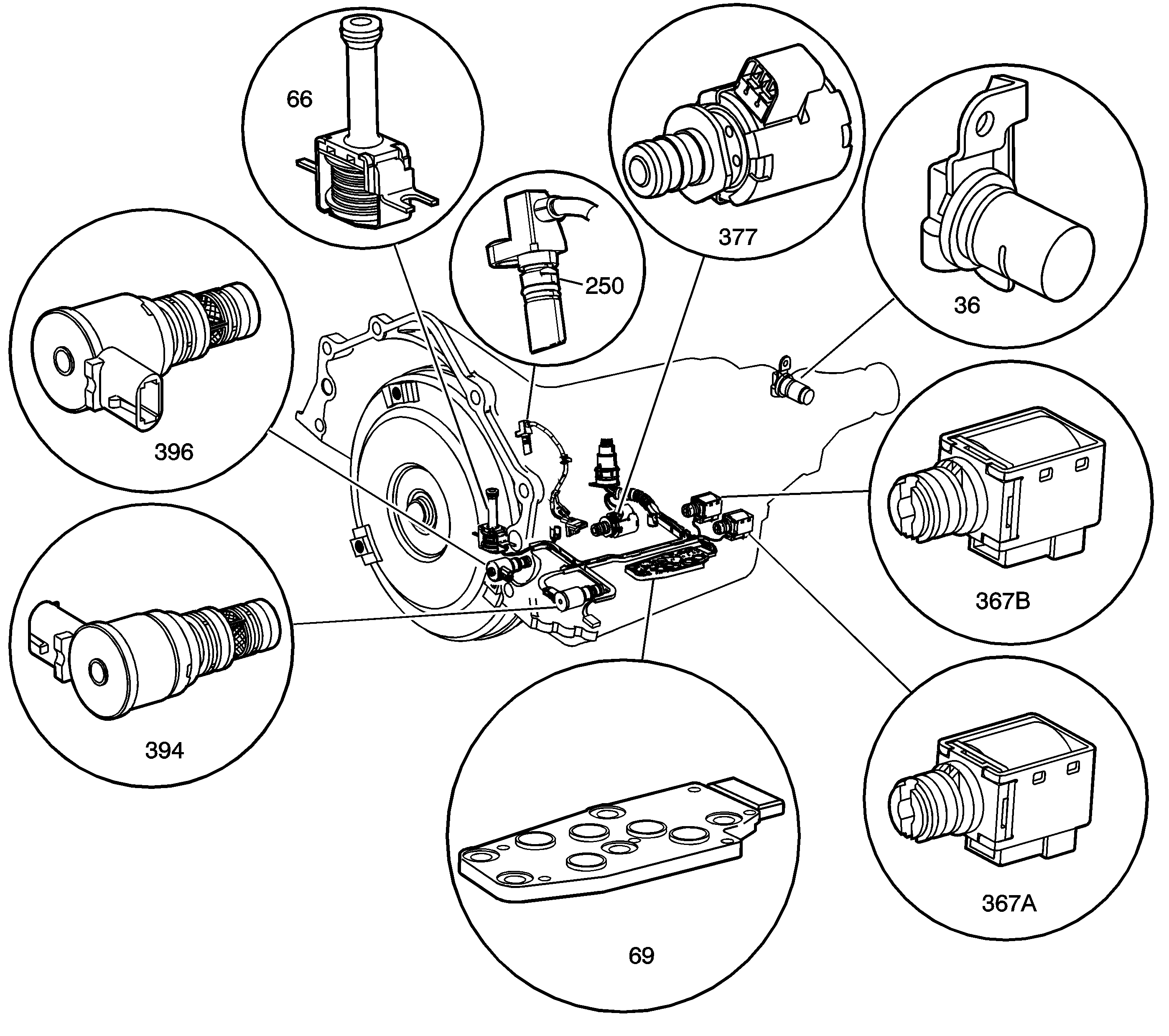

Object Number: 1552905  Size: LF
(36)Vehicle Speed Sensor (VSS)
(66)Torque Converter Clutch (TCC) Solenoid Valve
(69)Automatic Transmission Fluid Pressure Manual Valve Position Switch
(250)Input Speed Sensor (ISS)
(367a)1-2 Shift Solenoid (SS) Valve
(367b)2-3 Shift Solenoid (SS) Valve
(377)Pressure Control (PC) Solenoid Valve
(394)3-2 Shift Solenoid (SS) Valve
(396)Torque Converter Clutch (TCC) Pulse Width Modulation (PWM) Solenoid Valve
Figure 12:

Inside the Transmission Components (MT1)
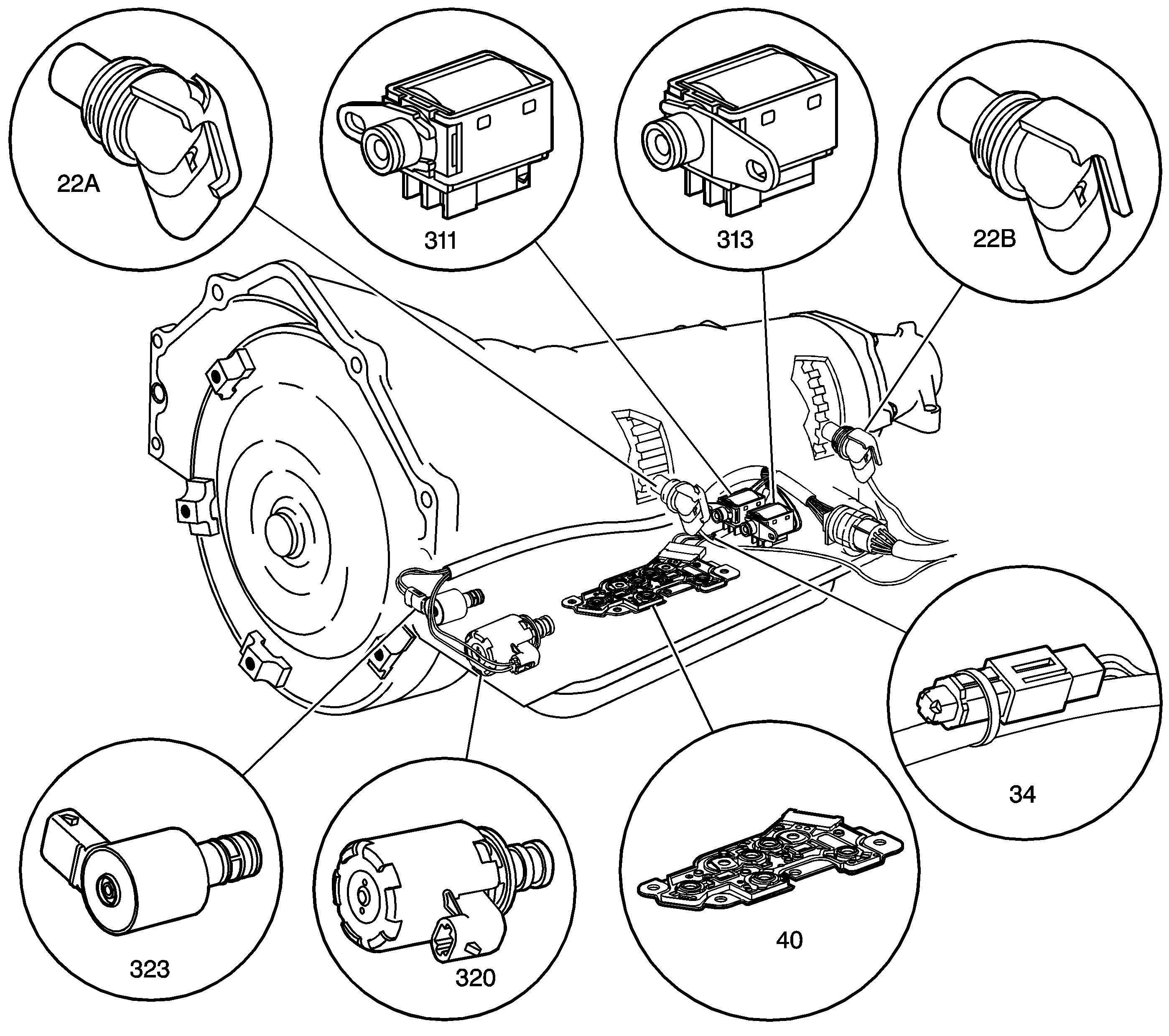

Object Number: 1236985  Size: LF
(22a)Input Speed Sensor (ISS)
(22b)Output Speed Sensor (OSS)
(34)Automatic Transmission Fluid Temperature (TFT) Sensor
(40)Automatic Transmission Fluid Pressure Manual Valve Position Switch
(311)2-3 Shift Solenoid (SS) Valve
(313)1-2 Shift Solenoid (SS) Valve
(320)Pressure Control (PC) Solenoid Valve Assembly
(323)Torque Converter Clutch (TCC) Pulse Width Modulation (PWM) Solenoid Valve
Figure 13:

Inside the Transmission Components (MYC or MYD)
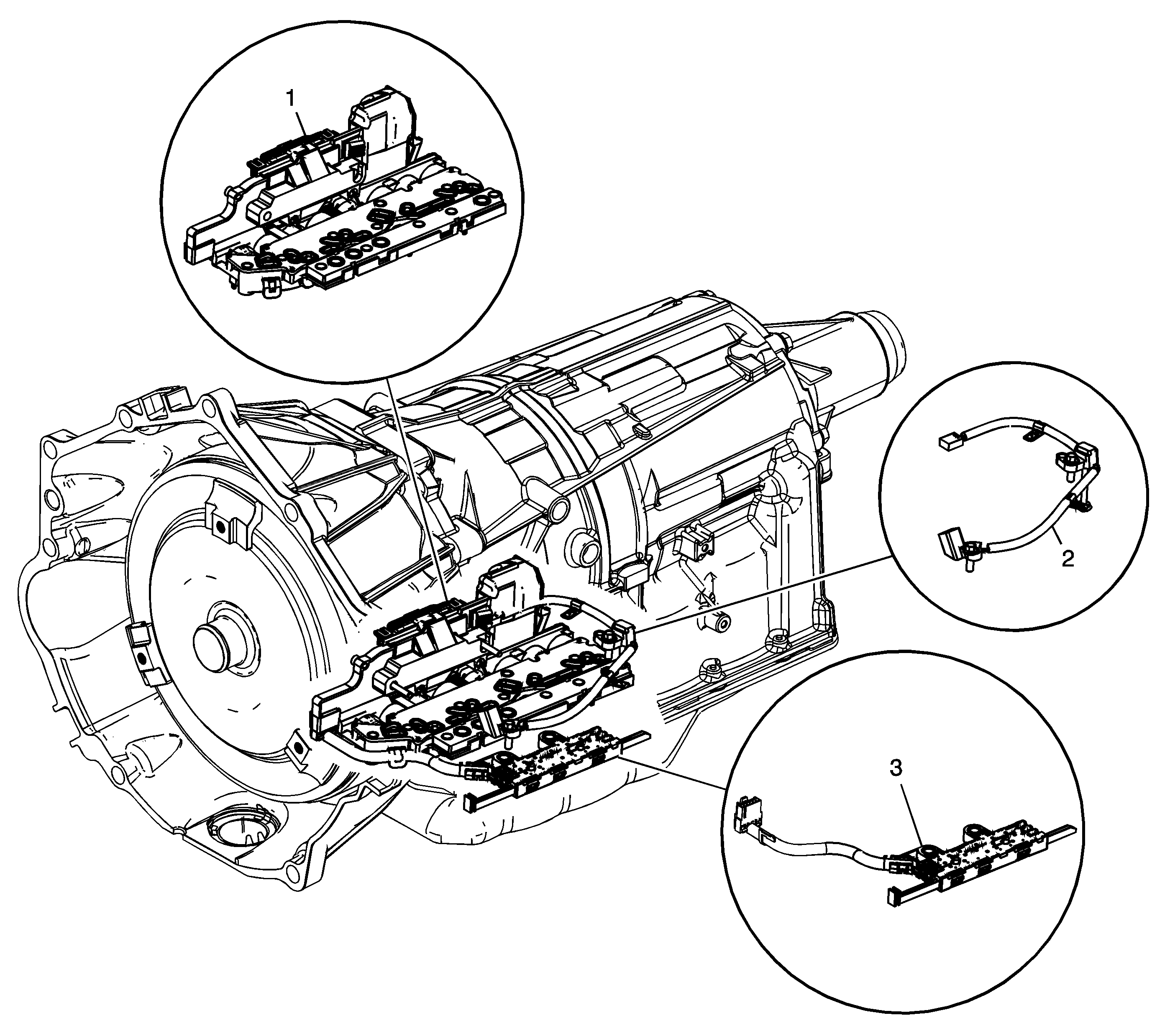

Object Number: 1696407  Size: LF
(1)Control Solenoid Valve Assembly
(2)Input Speed Sensor (ISS)/Output Speed Sensor (OSS)
(3)Automatic Transmission Internal Mode Switch (IMS)
Figure 14:

Hybrid Control Electronic Component Views
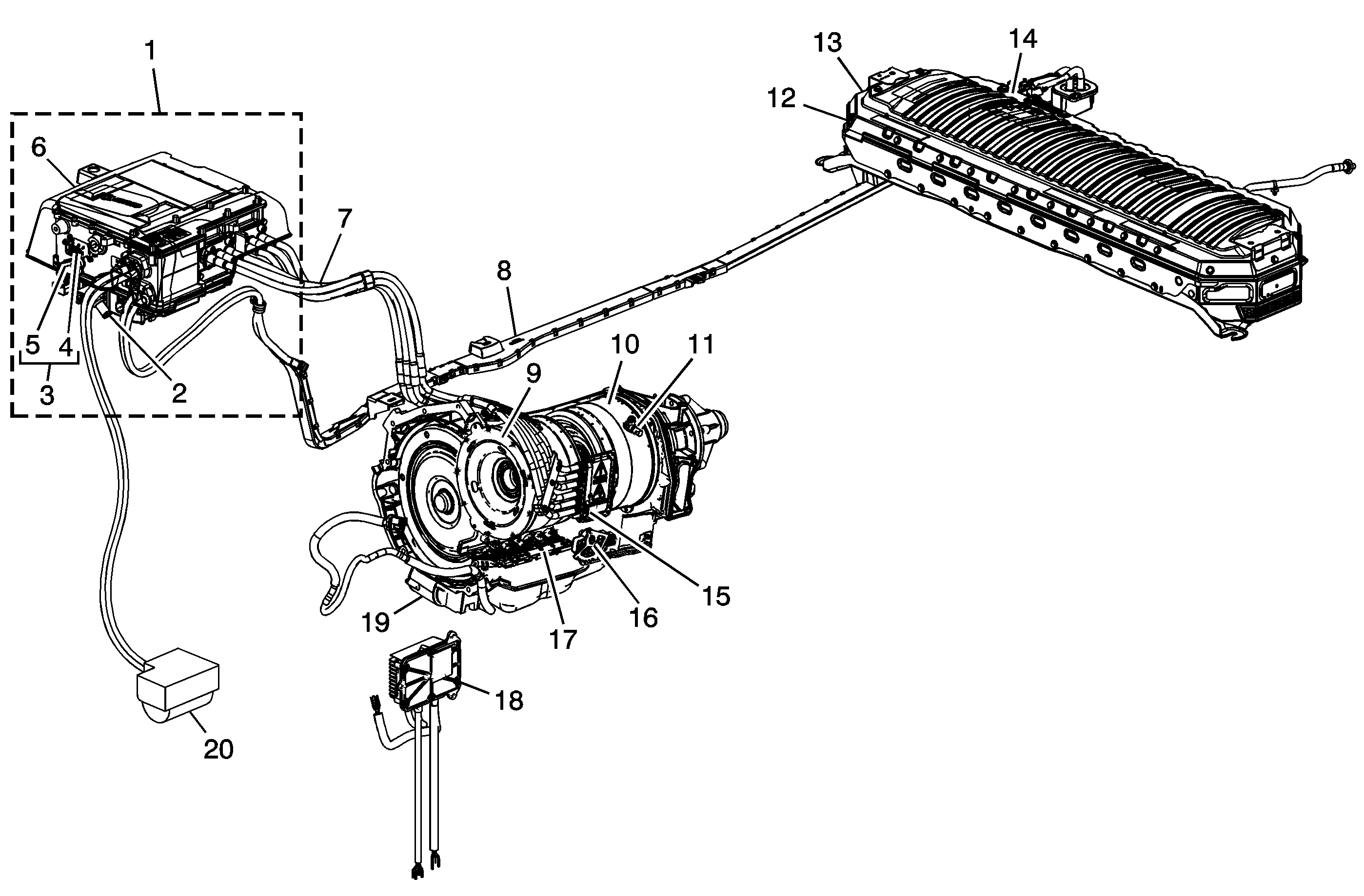

Object Number: 2008825  Size: MF
(1)Drive Motor Generator Control Module Assembly
(2)Accessory DC Power Control Module (APM) Assembly
(3)Drive Motor Generator Power Inverter Module (PIM) Assembly
(4)Hybrid Powertrain Control Module (HPCM)
(5)Motor Control Module (MCM) 1, Motor Control Module (MCM) 2
(6)Sight Shield Circuit Breaker
(7)Drive Motor Generator Power Inverter Module 3 Phase Cable Assembly
(8)Drive Motor Battery 300 Volt Positive and Negative Cable Assembly
(9)Drive Motor Generator Assembly - 1st Position
(10)Drive Motor Generator Assembly - 2nd Position
(11)A/Trans Output Speed Sensor Assembly
(12)Drive Motor Generator Battery
(13)Drive Motor Generator Battery Control Module Assembly
(14)Drive Motor Battery Cable Terminal Extension Cover Circuit Breaker
(15)Drive Motor Generator Power Inverter Module 3 Phase Cable Cover Circuit Breaker
(16)A/Trans Manual Shift Shaft Position Switch Assembly
(17)Control Solenoid w/Body and TCM Valve Assembly
(18)A/Trans Auxiliary Fluid Pump Control Module Assembly
(19)A/Trans Auxiliary Fluid Pump Assembly
(20)300 Volt AC Compressor w/Control Module Assembly