AIR BAG Indicator Illuminated, DTCs B0028, B0029, B0040, and B0041 Set (Replace Inflator Restraint Module Retainer CPA)

| Subject: | AIR BAG Indicator Illuminated, Side Impact Module DTCs B0028, B0029, B0040, and B0041 Set (Replace Inflator Restraint Passenger/Driver Seat Side Module Wiring Retainer (CPA) at side impact module connector in seat) |
| Models: | 2000 Chevrolet and GMC C/K Utility Models (Tahoe, Suburban, Yukon, Yukon XL) |
Condition
Some customers may comment that the AIR BAG indicator is illuminated on the instrument panel cluster (IPC).
Cause
The seat side module wiring retainer (CPA) may not be making proper contact with the shorting bar in the side impact module connector.
Correction
Caution: In order to avoid deploying the air bag when troubleshooting the SIR system, use only the equipment specified in this bulletin and the instructions given in this bulletin. Failure to use the specified equipment as instructed could cause air bag deployment, personal injury to you or someone else, or unnecessary SIR system repairs.
Caution: If any water has entered the vehicle's interior up to the level of the carpet or higher and soaks the carpet, the sensing and diagnostic module (SDM) and the SDM harness connector may need to be replaced. The SDM could be activated when powered, which could cause deployment of the air bag(s) and result in personal injury. Before attempting these procedures, the SIR system must be disabled.
Important: With the ignition OFF, inspect the SDM mounting area, including the
carpet. If any significant soaking or evidence of significant soaking is detected,
you must perform the following steps:
Failure to follow these steps could result in possible air bag deployment,
personal injury, or otherwise unneeded SIR system repairs.
The following diagnostic procedure will help you find and repair SIR system malfunctions for DTCs B0028, B0029, B0040 and B0041. For best results follow the sequence listed below.
Step | Action | Yes | No |
|---|---|---|---|
1 | Ignition switch OFF for 15 seconds. Turn the ignition switch to the ON position and note the AIR BAG indicator. Does the AIR BAG indicator flash seven times? | Go to Step 2 | Go to service information for Symptoms in the SIR subsection. |
2 | Connect a scan tool. Does the scan tool power up? | Go to Step 3 | Go to service information for Scan Tool Does Not Power Up diagnostic in the Data Link Communications subsection. |
3 | Attempt to establish communication with the inflatable restraint sensing and diagnostic module (SDM) and the instrument Panel Cluster (IPC). Were you successful? | Go to Step 4 | Go to service information for Scan Tool Does Not Communicate with Class 2 Device diagnostic in the Data Link Communications subsection. |
4 |
Does the scan tool display any DTCs? | Go to Step 5 | System OK |
5 | Did the scan tool display DTC B0028, B0029, B0040, or B0041? | Continue with the procedure below. | Exit this procedure and refer to service information for other DTCs. |
Disabling the SIR System
- Set both seats in the following positions:
- Turn OFF the ignition.
- Remove the key from the ignition switch.
- Remove the fuse box cover from the left end of the instrument panel (IP).
- Remove the AIR BAG fuse from the fuse block.
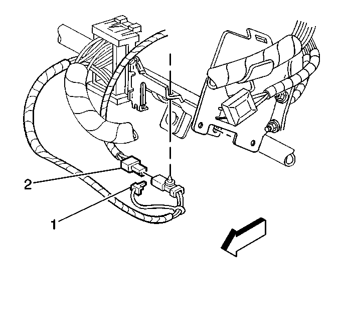
- Remove the CPA (1) from the driver side air bag yellow 2-way connector and disconnect the connector (2) located on the IP lower tie bar brace.
- Open the IP compartment door and remove all customer materials. Depress the limit stop on the right side of the IP compartment in order to allow the door to swing completely open.
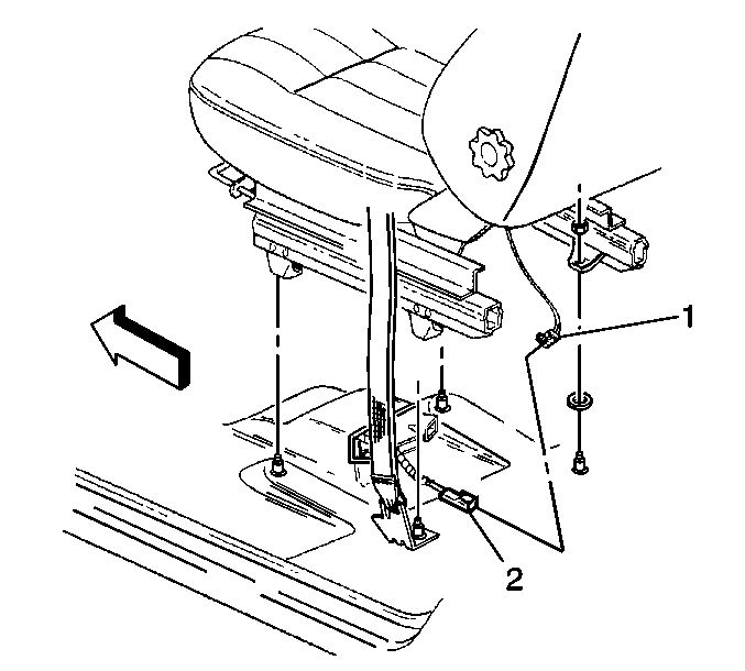
- Remove the CPA and disconnect the passenger side air bag yellow 2-way connector (2) located under the seat.
- Remove the CPA and disconnect the driver's side air bag yellow 2-way connector (2) located under the seat.
| • | Full-forward position |
| • | Rear seat cushion down |
| • | Lumbar fully collapsed |
| • | Seat recliner upright |
Important: When the AIR BAG fuse removed, and the ignition switch is in the RUN position, the AIR BAG indicator illuminates. This is normal operation and does not indicate an SIR system malfunction.


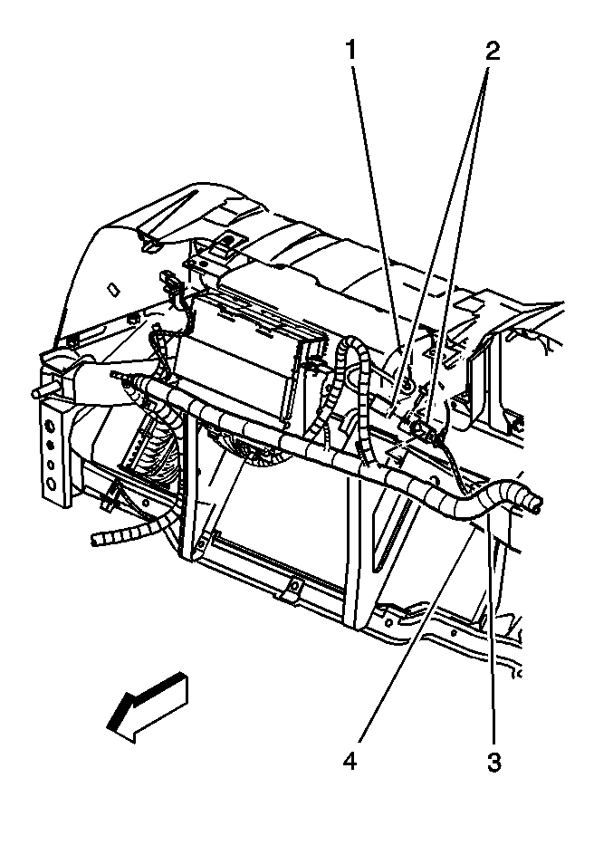
Looking in the smaller opening at the top of the IP, you will notice a large metal bar running cross-vehicle (4). On the back side of this bar is the passenger side inflator module yellow 2-way connector (2). Using a small pry bar, disengage the retainer from the bar allowing the passenger side inflator module yellow 2-way connector to hang loose. Remove the CPA from the passenger side inflator module yellow 2-way connector and disconnect the connector.

Replacing the CPA
- Starting with the passenger side front seat, disengage the J-strip retainer at the bottom rear of the seat backrest cover.
- Remove the two pushpins that hold the seat cover wings to the seat cover backing and frame.
- Recline the backrest of the seat as far as possible. Collapse the lumbar and side bolster bags of the seat. It may be necessary to turn the key to the ON position if equipped with a power seatback recliner and bolster.
- Turn the key to the OFF position.
- For seats with a self-contained center armrest, continue with step 6. Otherwise, go to step 9.
- Using a side-to-side motion, gently peel the backrest cover up over itself, turning it inside out, in order to access the armrest retaining clip.
- Remove the retaining clip. Access this from the front side of the seat.
- Gently pull the armrest out from the side of the seat.
- Using a side-to-side motion, gently peel the backrest cover up over itself, turning it inside out as you go, high enough to enable access to the interface of the wiring and the side impact module.
- Remove the factory installed CPA and install a new part number, #88938604. The yellow plastic CPA has a number printed on it that represents the Julian date that the CPA was manufactured. Be sure the number is 177 00 or larger.
- Reinstall the armrest clip to its position on the seat frame, if equipped with a self-contained armrest.
- Using a side-to-side motion, reposition the backrest cover in its original orientation.
- Reinstall the armrest by inserting the pivot through the cover and through the seat frame. Ensure the pivot is snapped into place properly, if equipped with a self-contained armrest.
- Reinstall the plastic pushpins through the designated holes in the seat trim wings, the seat back backing, and the seat frame.
- Engage the J-strip retainer at the bottom rear of the seat backrest cover.
- Repeat as necessary all steps on the drivers side front seat backrest.
Enabling the SIR System
- Ensure the ignition is in the OFF position and the key removed from the ignition key lock cylinder.
- Connect the passenger side air bag yellow 2-way connector (1) to the vehicle harness yellow 2-way connector and install the CPA (2) under the passenger seat.
- Connect the passenger side inflator module yellow 2-way connector (2) to the vehicle harness yellow 2-way connector. Install the CPA and position the retaining clip into the cross-vehicle bar (4).
- Lift up on the IP compartment door. Depress the open stop while closing the door so that the door will stay in the proper position when open.
- Return the customer items to the IP compartment and close the door.
- Connect the driver side inflator module yellow 2-way connector to the vehicle harness yellow 2-way connector and install the CPA under the driver seat.
- Connect the driver yellow 2-way connector (2) to the vehicle harness yellow 2-way connector located under the IP. Install the CPA and the clip to the cross-vehicle IP brace.
- Install the AIR BAG fuse into the fuse block.
- Install the fuse box door panel to the IP.
- Staying well away from all air bags, turn ON the ignition. The AIR BAG indicator will flash seven times, then turn off.
- Connect the Tech 2 to the vehicle and clear all DTCs.
- Perform the Diagnostic System Check - SIR if the AIR BAG indicator lamp does not operate as described. Refer to published service information in the SIR subsection for other conditions.


Parts Information
Part Number | Description | Qty |
|---|---|---|
88938604 | Retainer, Inflatable Restraint Passenger/Driver Seat Side Module | 1 pkg. (2 retainers per pkg.) |
Parts are expected to be available on 12-11-2000 from GMSPO.
Warranty Information
For vehicles repair under warranty, use:
Labor Operation | Description | Labor Time |
|---|---|---|
N6624 | Wiring and/or connector repair Occupant Safety | 0.8 hr |
