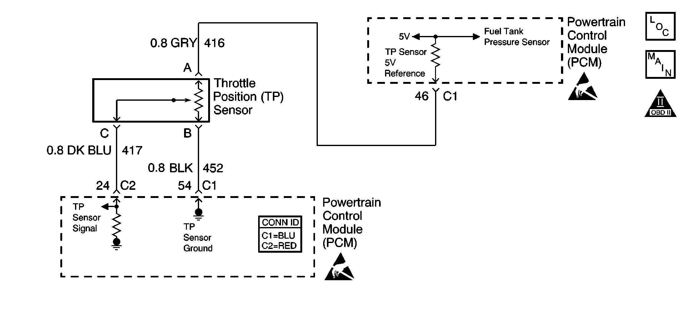
Circuit Description
The throttle position (TP) sensor is a potentiometer. The TP sensor is mounted to the left side of the throttle body. The TP sensor provides a voltage signal that changes relative to throttle blade angle. This signal voltage is one of the most important inputs used by the powertrain control module (PCM). The TP sensor has a 5 volt reference, a ground, and a signal circuit.
The TP sensor signal voltage should be below 1 volt at idle. The TP sensor voltage should increase to above 4 volts at wide open throttle (WOT).
This DTC will set when the PCM senses a signal voltage lower than the normal operating range of the sensor.
Conditions for Running the DTC
The ignition switch is in the run position.
Conditions for Setting the DTC
| • | The TP sensor voltage is less than 0.2 volts. |
| • | The intermittent condition exists for a total of 1 second during a 20 second time period. |
Action Taken When the DTC Sets
| • | The powertrain control module (PCM) stores the DTC information into memory when the diagnostic runs and fails. |
| • | The malfunction indicator lamp (MIL) will not illuminate. |
| • | The PCM records the operating conditions at the time the diagnostic fails. The PCM stores this information in the Failure Records. |
Conditions for Clearing the DTC
| • | A last test failed, or current DTC, clears when the diagnostic runs and does not fail. |
| • | A history DTC will clear after 40 consecutive warm-up cycles, if no failures are reported by this or any other non-emission related diagnostic. |
| • | Use a scan tool in order to clear the DTC. |
Diagnostic Aids
Important: Remove any debris from the PCM connector surfaces before servicing the PCM. Inspect the PCM connector gaskets when diagnosing or replacing the PCM. Ensure that the gaskets are installed correctly. The gaskets prevent water intrusion into the PCM.
An intermittent DTC can be caused by electromagnetic interference (EMI). Inspect related circuits for being too close to secondary ignition wires and the generator.
For an intermittent, refer to Symptoms .
Test Description
The numbers below refer to the step numbers on the diagnostic table.
-
If DTC P0122 failed this ignition, this indicates a hard failure is present. When a hard failure is present, both the hard and intermittent DTCs will set. The engine must be operating longer than 30 seconds to verify if the DTC set.
-
When moving related connectors, visually and physically inspect connectors for the following:
-
When moving related wiring harnesses, visually and physically inspect wiring for the following:
-
Using Freeze Frame and Failure Records data may aid in locating an intermittent condition. If you cannot duplicate the DTC, the information included in the Freeze Frame and Failure Records data can be useful in determining how many miles since the DTC set. The Fail Counter and Pass Counter can also be used to determine how many ignition cycles the diagnostic reported a pass or a fail. Operate vehicle within the same Freeze Frame conditions, such as RPM, load, vehicle speed, temperature etc., that you observed. This isolates when the DTC failed.
| • | Poor mating of the connector halves or a terminal not fully seated, or backed out, in the connector body |
| • | Improperly formed or damaged terminals--Carefully reform or replace all connector terminals in the related circuits in order to insure proper terminal contact tension. |
| • | Poor terminal to wire connection--Inspect for poor crimps, crimping over wire insulation rather than the wire. |
| • | Dirt or corrosion on terminals. Inspect connector seals for being there and for being damaged |
| • | Wire insulation that is rubbed through, causing an intermittent short. |
| • | Wiring broken inside the insulation. |
Step | Action | Value(s) | Yes | No |
|---|---|---|---|---|
1 | Did you perform the Powertrain On-Board Diagnostic (OBD) System Check? | -- | ||
Did DTC P0122 fail this ignition ? | -- | Go to DTC P0122 Throttle Position (TP) Sensor Circuit Low Voltage | ||
Does the sensor value change abruptly while a related connector is being moved? | -- | |||
Observe the affected sensor value on the scan tool while moving the related wiring harnesses. Does the sensor value change abruptly while moving related electrical harnesses? | -- | |||
Does the scan tool indicate that this diagnostic failed this ignition? | -- | Go to Diagnostic Aids | ||
6 | Repair the damaged connectors and terminals. Refer to Repairing Connector Terminals in Wiring Systems. Is the action complete? | -- | -- | |
7 | Repair the circuit as necessary. Refer to Wiring Repairs in Wiring Systems. Is the action complete? | -- | -- | |
8 |
Is the action complete? | -- | -- | |
9 |
Does the scan tool indicate that this test ran and passed? | -- | ||
10 | Select the Capture Info option and the Review Info option using the scan tool. Does the scan tool display any DTCs that you have not diagnosed? | -- | Go to the applicable DTC table | System OK |
