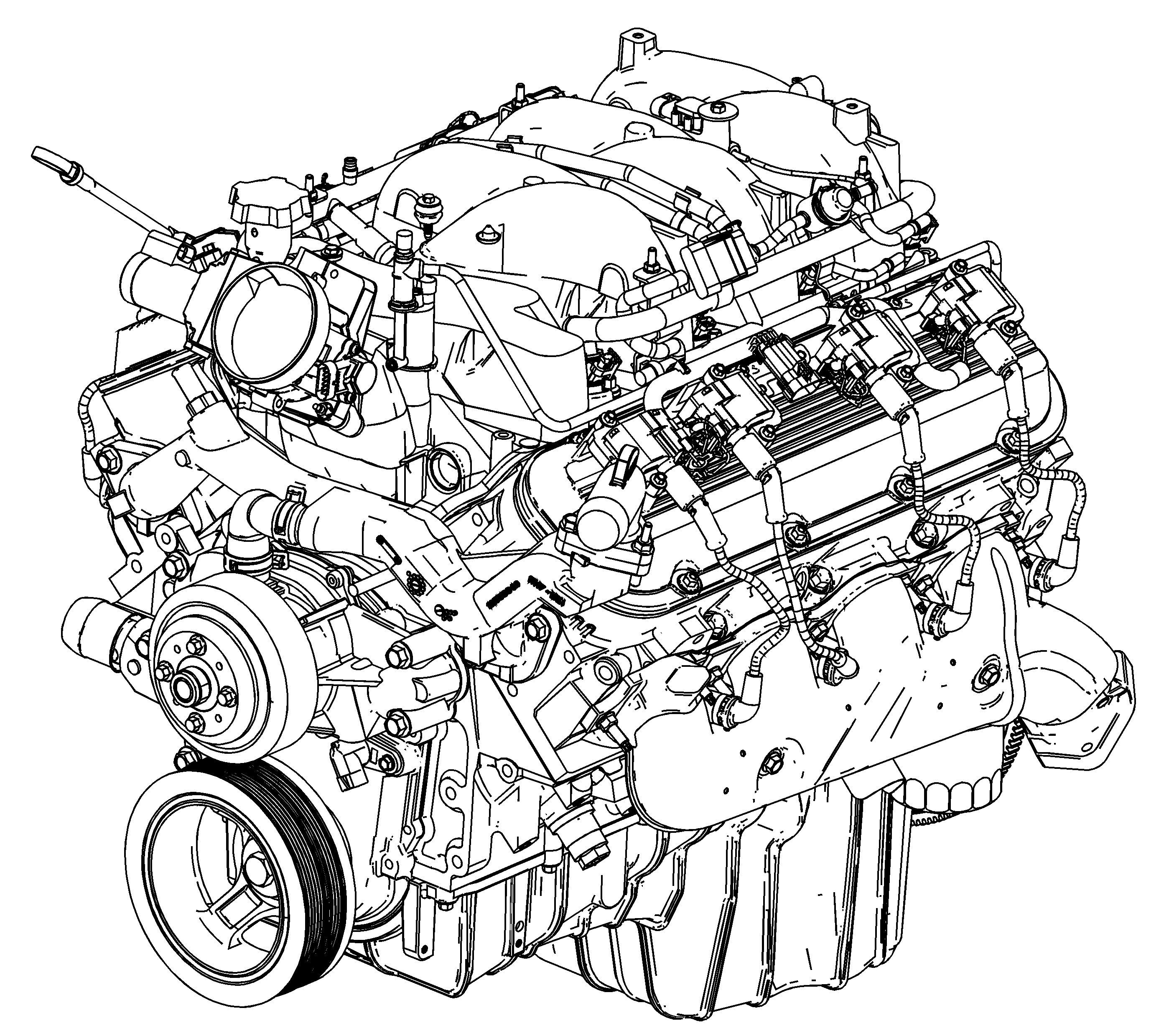
Cylinder Block
The engine block is made of cast iron and it has eight cylinders arranged in a 90 degree V shape with four cylinders in each bank. The engine block is a one piece casting with the cylinders encircled by coolant jackets.
Cylinder Head
The cylinder heads are made of cast iron and have parent metal intake valve guides and intake valve seats. The cast iron exhaust valve guides and powdered metal valve seats are pressed into the exhaust ports. A spark plug is located between the valves in the side of the cylinder head. The water crossover pipe attaches to the front of each cylinder head.
Camshaft
A steel camshaft is supported by five bearings pressed into the engine block. The camshaft sprocket is mounted to the front of the camshaft and is driven by the crankshaft sprocket through a camshaft timing chain.
Motion from the camshaft is transmitted to the valves by hydraulic roller valve lifters, valve push rods, and ball-pivot type rocker arms. Gear teeth are machined into the camshaft near the rear journal in order to drive a shaft assembly which operates the oil pump driveshaft. Ignition synchronization with the camshaft is provided by a physical feature integral with the camshaft sprocket.
Crankshaft
The crankshaft is made of cast nodular iron. The crankshaft is supported by five crankshaft bearings. The crankshaft bearings are retained by the crankshaft bearing caps. The crankshaft bearing caps are machined with the engine block for proper alignment and clearance. The crankshaft bearing caps are retained by two bolts and two studs each. The number five crankshaft bearing at the rear of the engine block is the end thrust bearing. The four connecting rod journals, two rods per journal, are spaced 90 degrees apart. The crankshaft position sensor reluctor ring is pushed onto the rear of the crankshaft. The crankshaft position sensor reluctor is constructed of powdered metal. The reluctor ring has an interference fit onto the crankshaft and an internal keyway for correct positioning.
Pistons and Connecting Rods
The pistons are cast aluminum alloy that use two compression rings and one oil control ring assembly. The piston pins are a floating fit in the pistons and the piston pins are retained by a press fit in the connecting rod assembly. The pistons are coated in order to create an interference fit into the cylinder. The connecting rods are forged steel and have precision insert type crankpin bearings. The piston and connecting rod is only serviced as an assembly.
Valve Train
The valve train is a ball pivot type. Motion is transmitted from the camshaft through the hydraulic roller valve lifters and tubular valve push rods to the valve rocker arms. The valve rocker arm pivots on a ball in order to open the valve. The hydraulic roller valve lifters keep all parts of the valve train in constant contact. Each valve lifter acts as an automatic adjuster and maintains zero lash in the valve train. This eliminates the need for periodic valve adjustment. The valve rocker arm stud and nut retains the valve rocker arm and ball seat. The valve rocker arm stud is threaded into the cylinder head. The valve stem seal is pressed over the valve guide of the cylinder head.
Intake Manifold
The intake manifold is a one-piece design. The intake manifold is made of cast aluminum. The throttle body is attached to the front of the intake manifold. The fuel rail assembly with eight separate fuel injectors is retained to the intake manifold by four studs. The fuel injectors are seated in their individual manifold bores with O-ring seals to provide sealing. A Manifold Absolute Pressure (MAP) sensor is mounted on the top of the intake manifold and sealed by an O-ring seal. The MAP sensor is held in place with a retainer bolt. The evaporative emission canister solenoid is located in the front of the intake manifold. The positive crankcase ventilation (PCV) system is internally cast into the intake manifold. There is not a PCV valve. A splash shield is installed under the intake manifold. The shield prevents hot oil from contacting the bottom of the intake manifold, maintaining air inlet charge density.
Exhaust Manifold
The two exhaust manifolds are constructed of cast stainless steel. The exhaust manifolds direct exhaust gases from the combustion chambers to the exhaust system.
