Removal Procedure
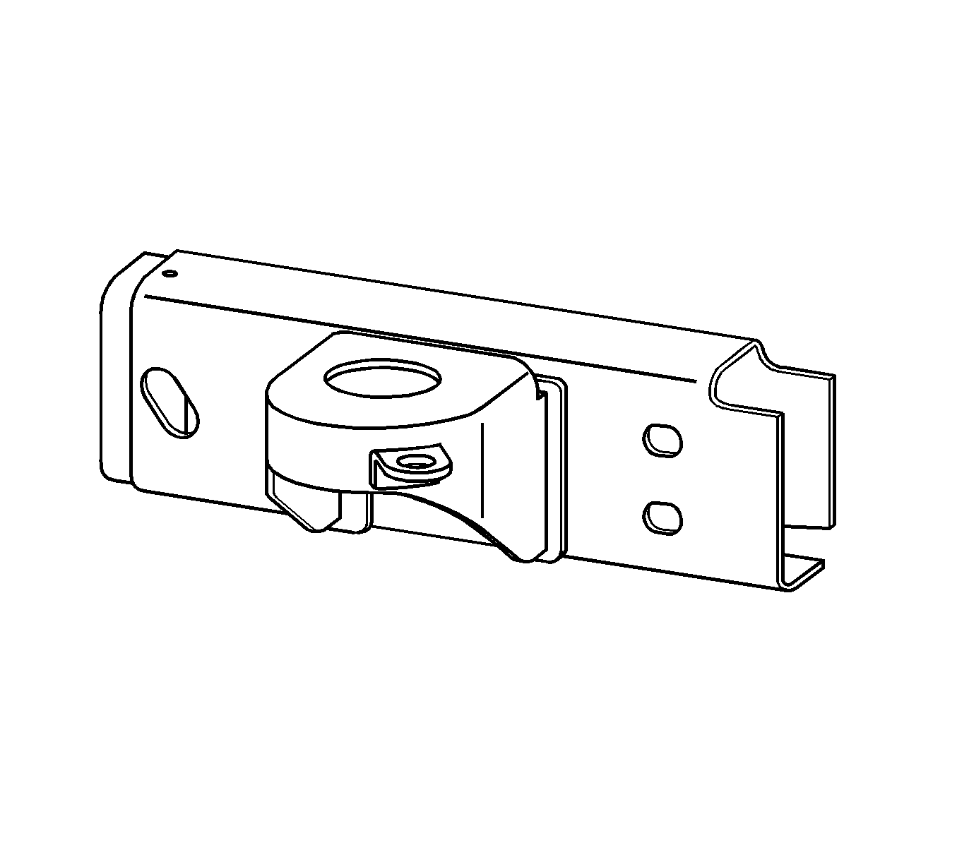
The service assembly for the left and the right rear frame rails is pre-sleeved, mild steel, hydro-formed parts. The assembly includes the body support mounting bracket, a trailer hitch and rear bumper mounting holes.
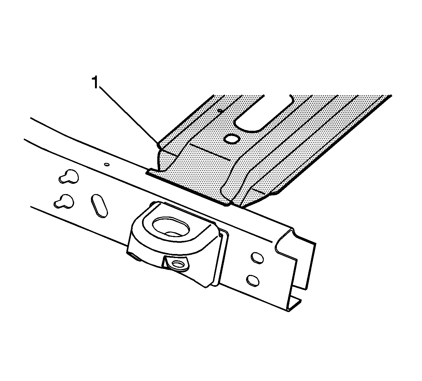
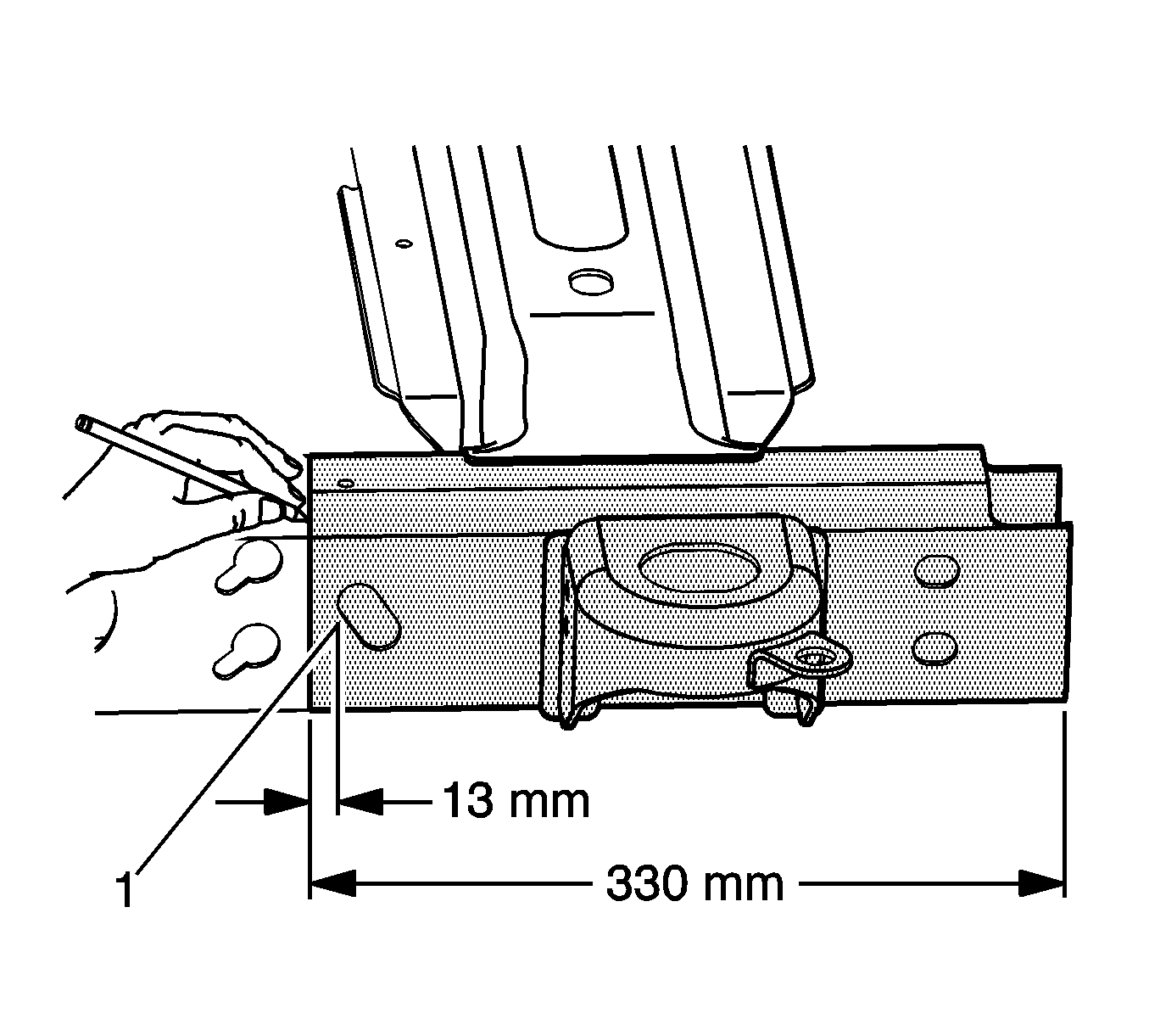
Important: The position of the rear cross-member (1) varies upon the wheel-base of the vehicle. This procedure applies to all vehicles.
- Disconnect the negative battery cable. Refer to Battery Negative Cable Disconnection and Connection .
- Remove all of the related panels and components.
- Repair as much of the damage as possible to factory specifications.
- Locate the sectioning location by measuring 13 mm forward from the shipping slot (1) or 330 mm forward of the frame rail end. Scribe a line around the rail.
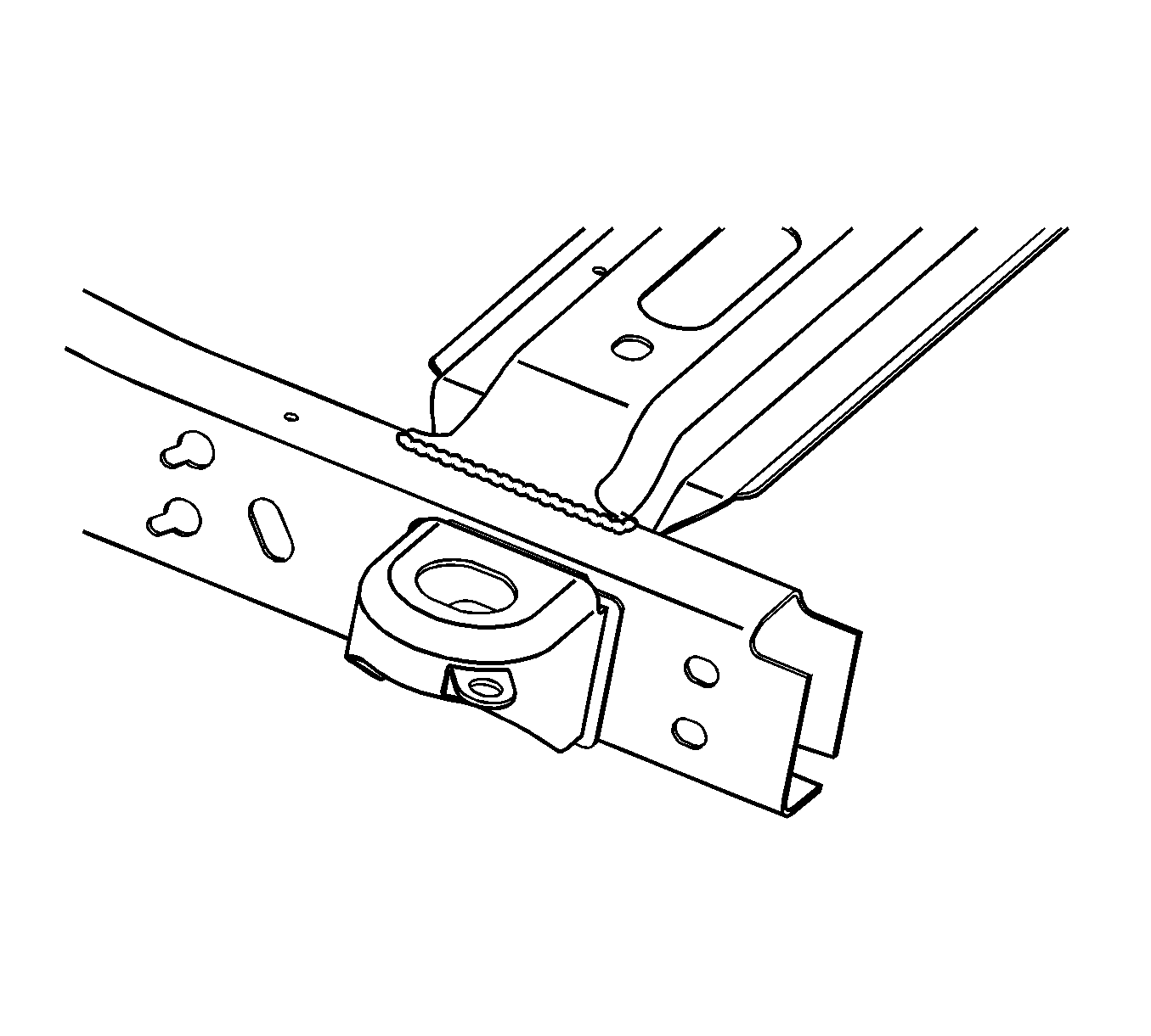
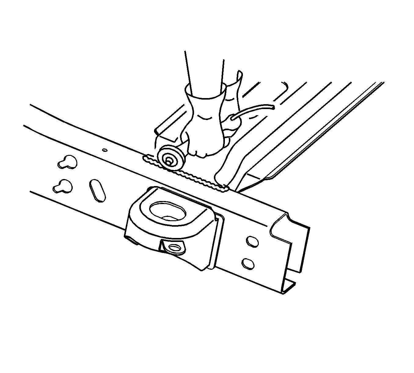
- Using a cut-off wheel or equivalent, remove the weld which attaches the rear cross-member to the damaged frame rail.
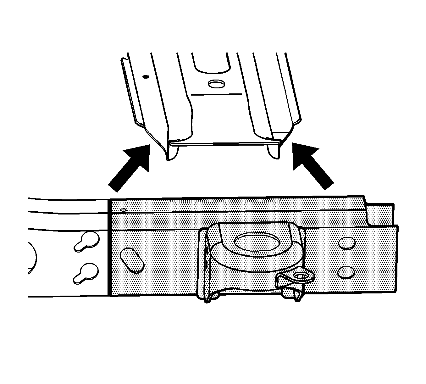
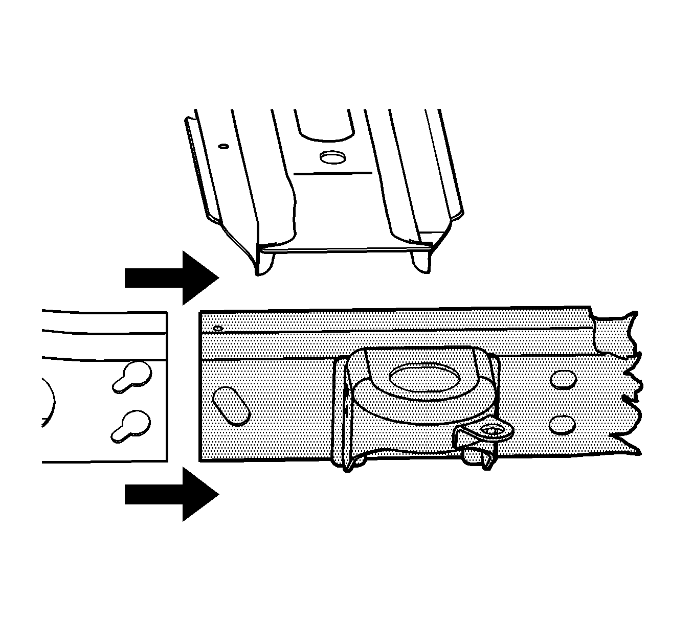
- Move the cross-member clear of the damaged frame rail.
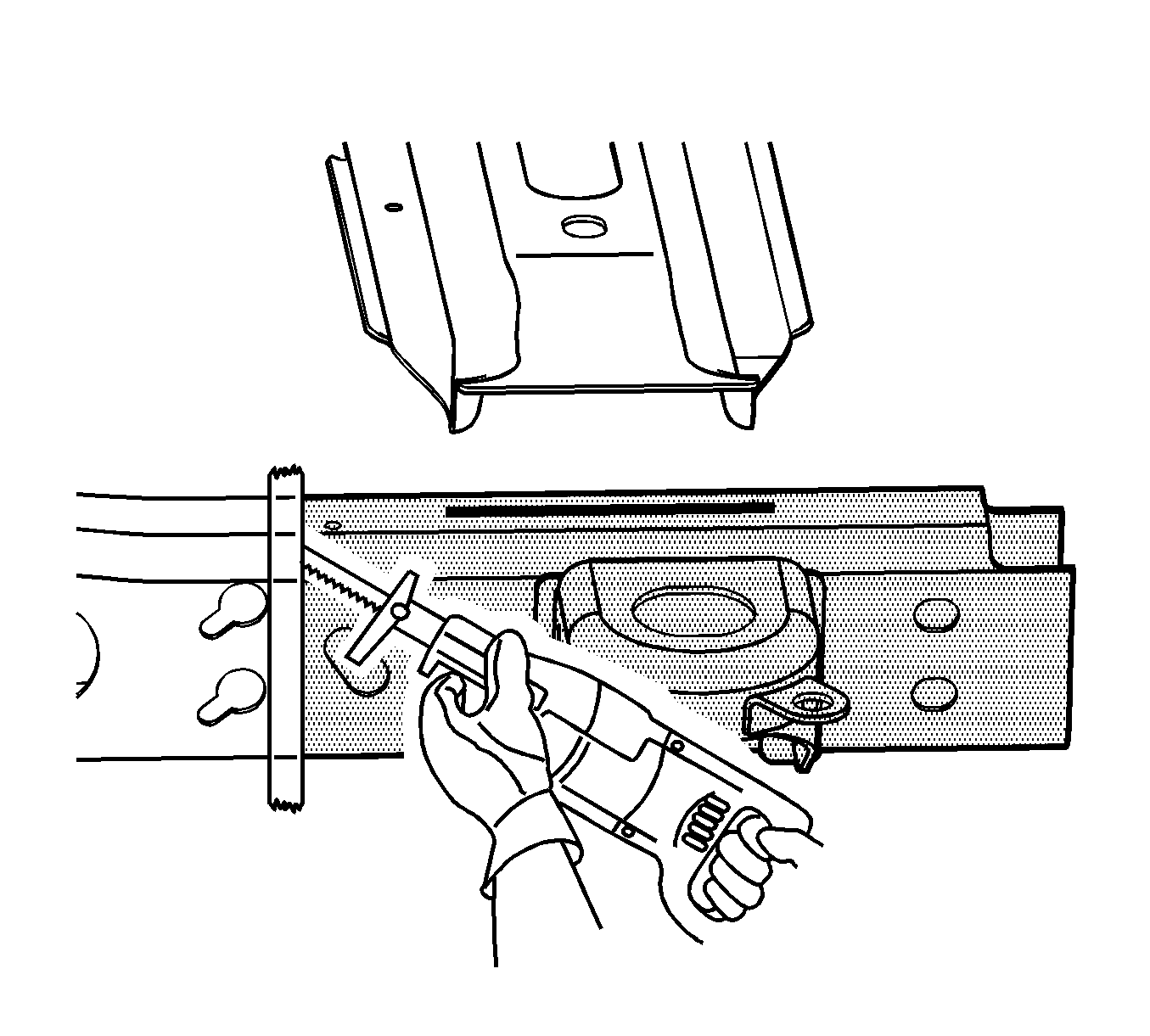
- Apply masking tape next to the sectioning location and around the frame as shown.
- Cut the damaged frame rail along the sectioning location using a reciprocating saw or equivalent, as shown.
- Remove the damaged frame section.
Caution: Refer to Approved Equipment for Collision Repair Caution in the Preface section.
Caution: Refer to Collision Sectioning Caution in the Preface section.
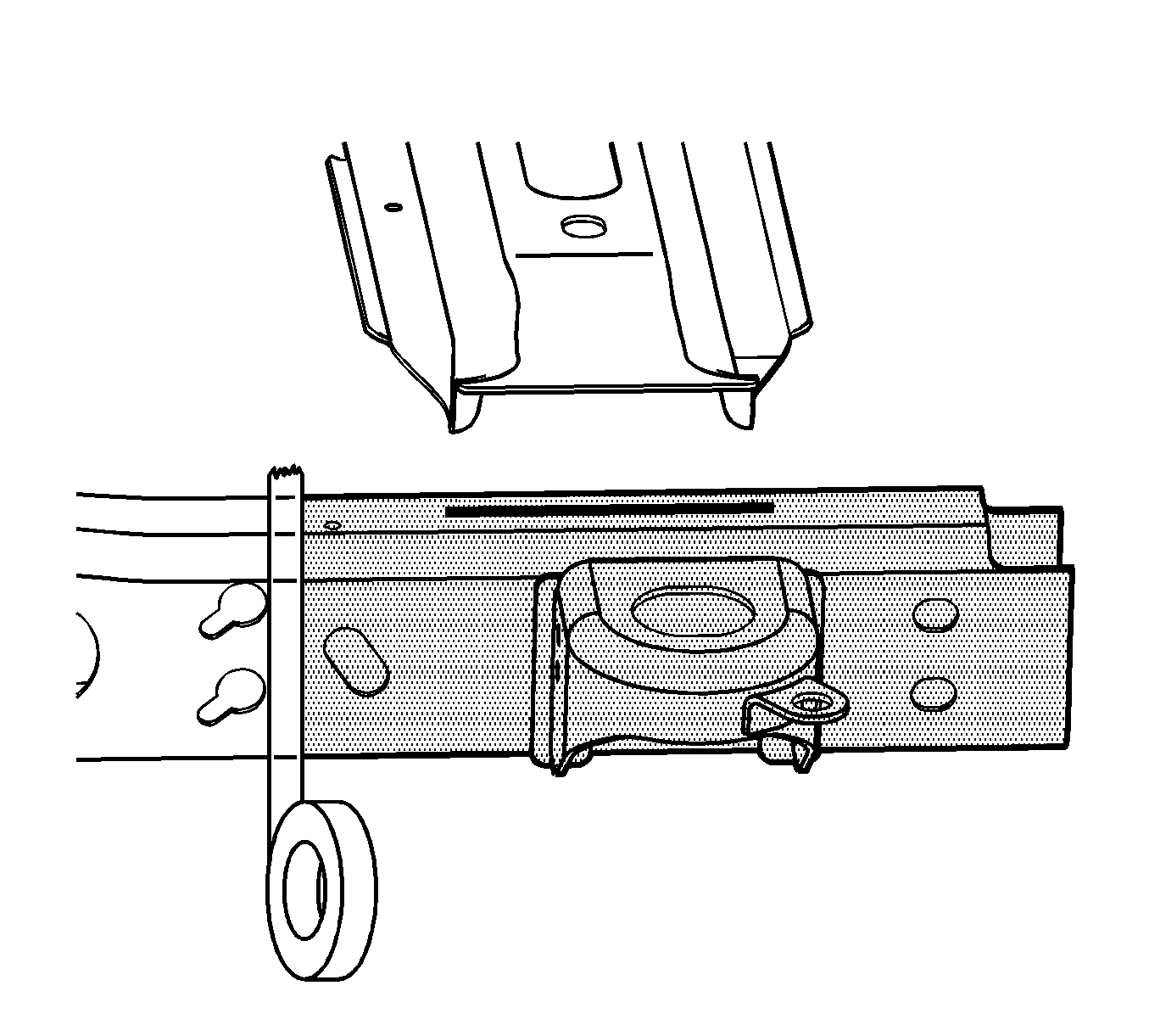
Important: Align the edge of the masking tape with the sectioning location.
Installation Procedure
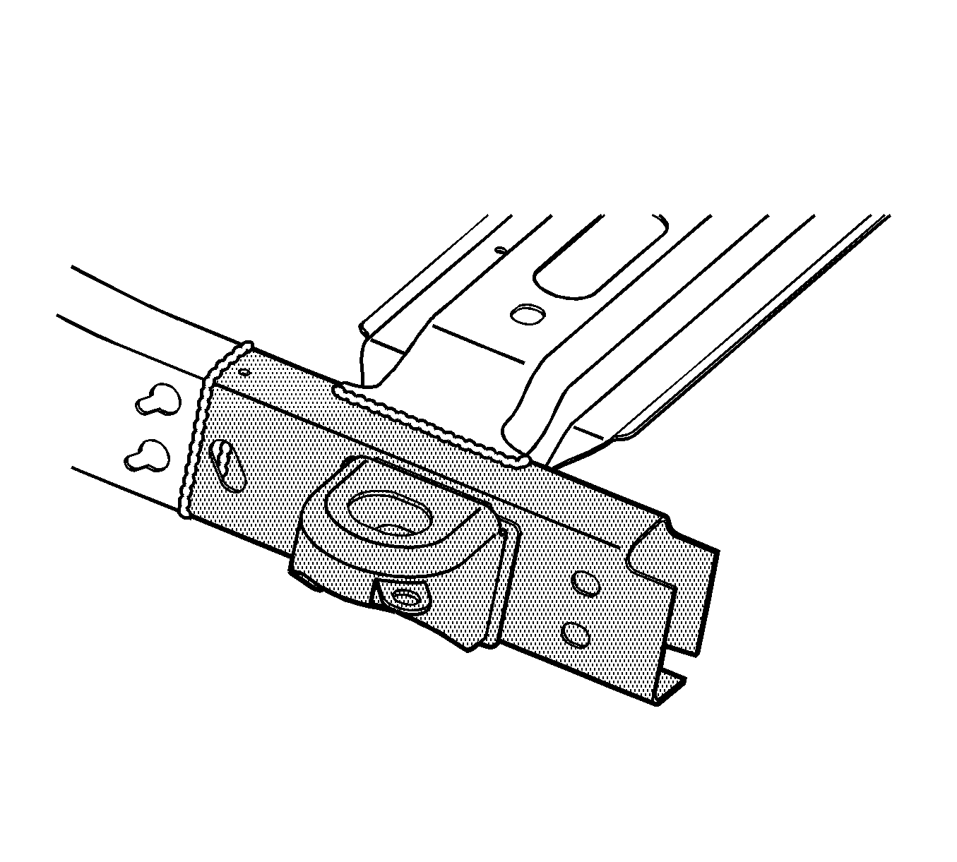
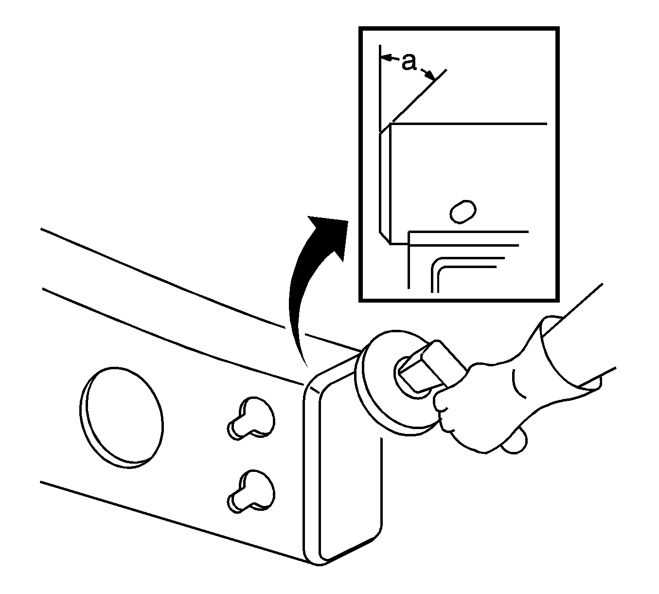
- Grind the existing frame rail sectioning location to a 45 degree angle, as shown in the figure.
- Prepare all of the attaching surfaces as necessary.
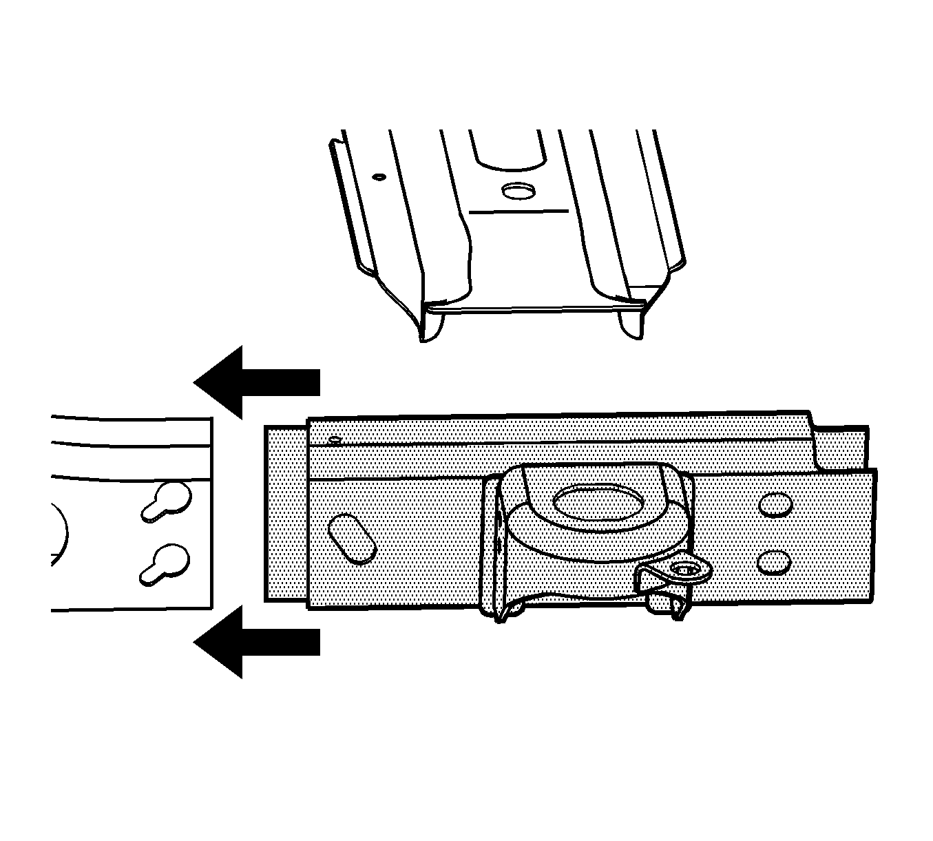
- Position the service frame section to the existing frame and clamp in place.
- Continuous-weld the sectioning location completely around the rail.
- Lower and clamp the rear cross-member in place.
- Continuous-weld the cross-member to the frame rail.
- Clean and prepare all of the welded surfaces.
- Apply the sealers and anti-corrosion materials to the repair area, as necessary. Refer to Anti-Corrosion Treatment and Repair .
- Install all of the related panels and components.
- Connect the negative battery cable. Refer to Battery Negative Cable Disconnection and Connection .
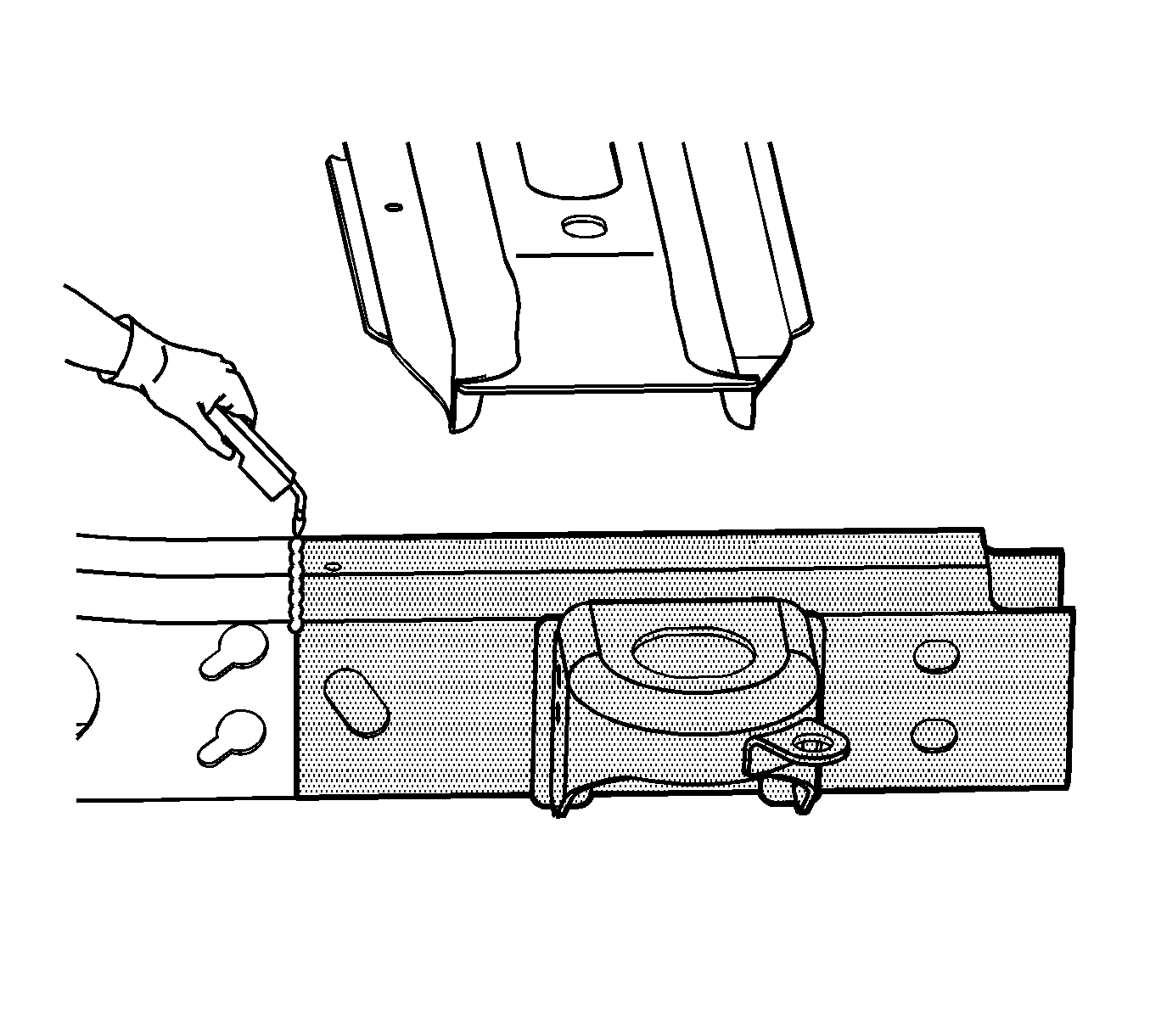
Important: Inspect the frame measurements three-dimensionally to ensure proper position of the service frame prior to welding.
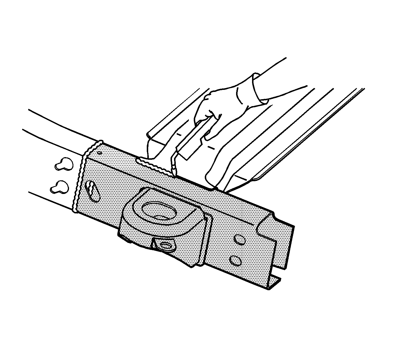
Important: Inspect the frame measurements three-dimensionally to ensure the proper position of the rear cross-member.
