Steering Gear Replacement Non-Rack and Pinion
Special Tools
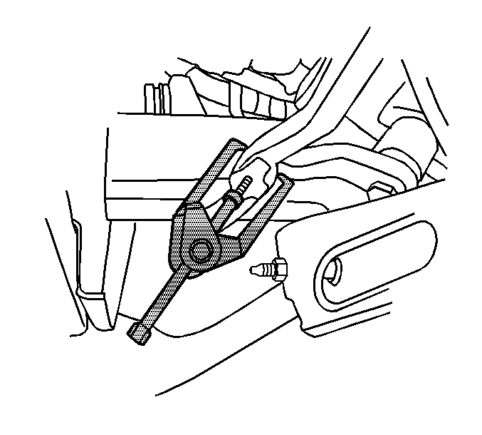
J 24319-B Steering Linkage and Tie Rod Puller
Removal Procedure
- Remove as much power steering fluid from the power steering fluid reservoir as possible.
- Place drain pans under the vehicle as needed.
- Raise and support the vehicle. Refer to Lifting and Jacking the Vehicle.
- Remove the engine shield, if equipped. Refer to Engine Shield Replacement.
- If equipped with a diesel engine, remove the left wheelhouse liner. Refer to Front Wheelhouse Liner Replacement - Left Side.
- Disconnect the steering hoses from the steering gear.
- Disconnect the steering shaft coupling from the steering gear. Refer to Steering Shaft Coupling Replacement.
- Remove the pitman arm nut (1).
- Separate the pitman arm from the relay rod using puller J 24319-B .
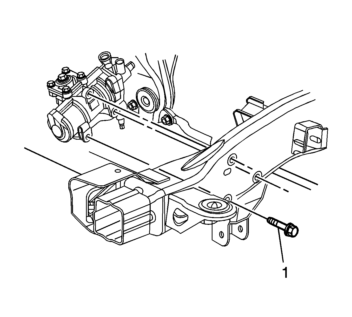
- Remove the steering gear bolts (1).
- Remove the steering gear from the vehicle.
- Transfer the pitman arm as necessary. Refer to Pitman Arm Replacement.
Caution: Refer to Power Steering Hose Disconnected Caution in the Preface section.
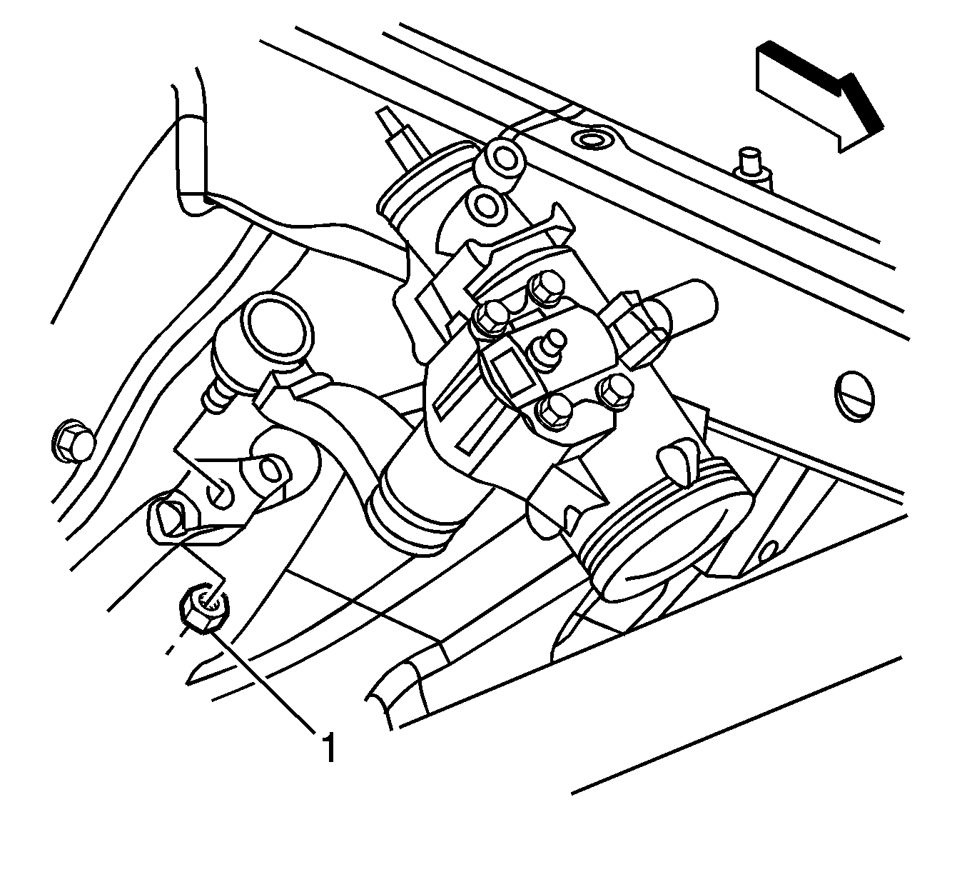
Note: Discard the pitman arm nut.
Installation Procedure
- Install the pitman arm if necessary. Refer to Pitman Arm Replacement.
- Install the steering gear to the vehicle.
- Install the steering gear bolts (1).
- Install the pitman arm to the relay rod.
- Install the pitman arm nut (1).
- Connect the power steering hoses to the steering gear.
- Connect the steering shaft coupling. Refer to Steering Shaft Coupling Replacement.
- Clean any excess fluid from the vehicle and remove the drain pans.
- If equipped with a diesel engine, install the left wheelhouse liner. Refer to Front Wheelhouse Liner Replacement - Left Side.
- Install the engine shield, if equipped. Refer to Engine Shield Replacement.
- Lower the vehicle.
- Fill and bleed the power steering system. Refer to Power Steering System Bleeding.
Caution: Refer to Fastener Caution in the Preface section.

Note: Start all of the steering gear bolts by hand and fully seat them before finalizing the torque.
Tighten
Tighten the bolts to 150 N·m (110 lb ft).

Tighten
Tighten the nut to 62 N·m (46 lb ft).
Tighten
Tighten the hoses fittings to 32 N·m (24 lb ft).
Steering Gear Replacement Rack and Pinion
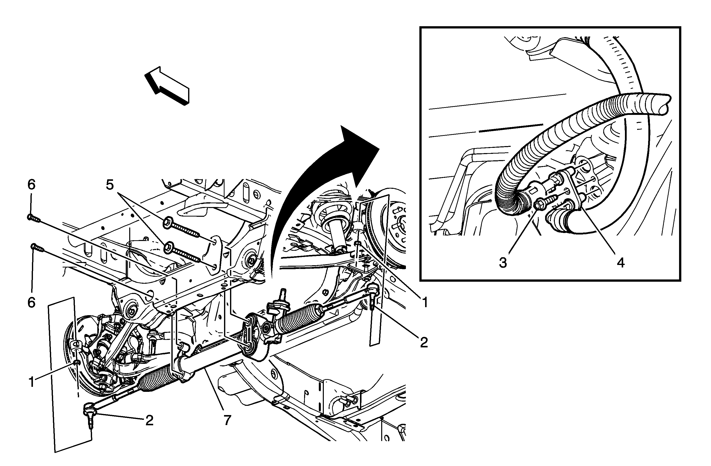
Callout | Component Name | ||||
|---|---|---|---|---|---|
Preliminary Procedures
| |||||
1 | Steering Linkage Outer Tie Rod Nut (Qty: 2) Caution: Do not attempt to disconnect a steering linkage joint by driving a wedge between the joint and the attached part. Seal damage may result which will cause premature failure of the joint. Caution: Refer to Fastener Caution in the Preface section. Tighten | ||||
2 | Steering Linkage Outer Tie Rod (Qty: 2) ProcedureUse puller J 24319-B to separate the steering linkage outer tie rods from the steering knuckles. | ||||
3 | Power Steering Gear Inlet Hose Retaining Plate Bolt Procedure
Tighten | ||||
4 | Power Steering Gear Inlet/Outlet Hose (Qty: 2) Caution: Refer to Power Steering Hose Disconnected Caution in the Preface section. ProcedurePull the power steering gear inlet/outlet hoses out of the steering gear. Tip | ||||
5 | Left Side Steering Gear Bolt (Qty: 2) Tighten | ||||
6 | Right Side Steering Gear Bolt (Qty: 2) Tighten | ||||
7 | Steering Gear Procedure
Special Tools
| ||||
Steering Gear Replacement Two Mode Hybrid
Removal Procedure
- Perform the high voltage disabling procedure. Refer to High Voltage Disabling.
- Remove the front tire and wheel assemblies. Refer to Tire and Wheel Removal and Installation.
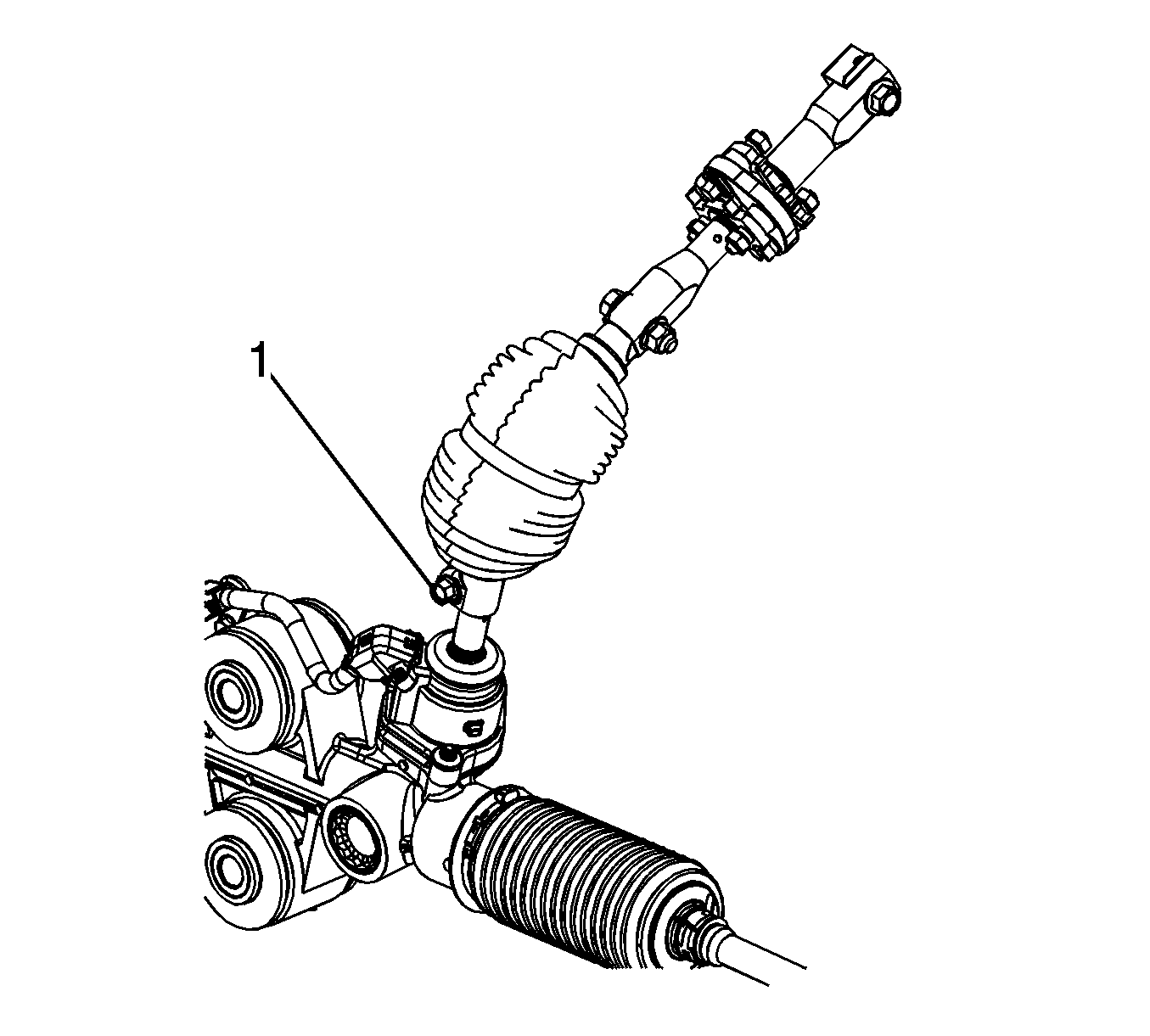
- Remove the steering shaft coupling bolt (1) at the steering gear.
- Separate the steering shaft coupling from the steering gear.
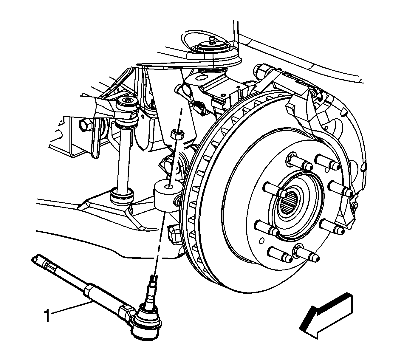
- Remove the steering linkage outer tie rod nuts from the steering linkage outer tie rods (1) and discard them.
- Separate the steering linkage outer tie rods from the steering knuckles.
- Support the steering gear with jackstands.
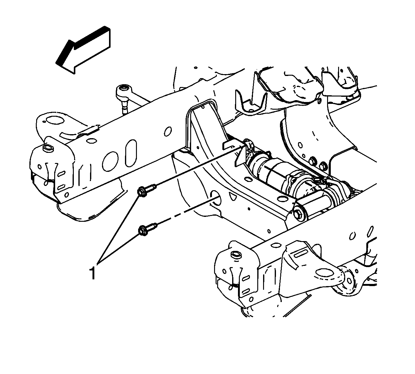
- Remove the steering gear bolts (1) from the left side of the steering gear.
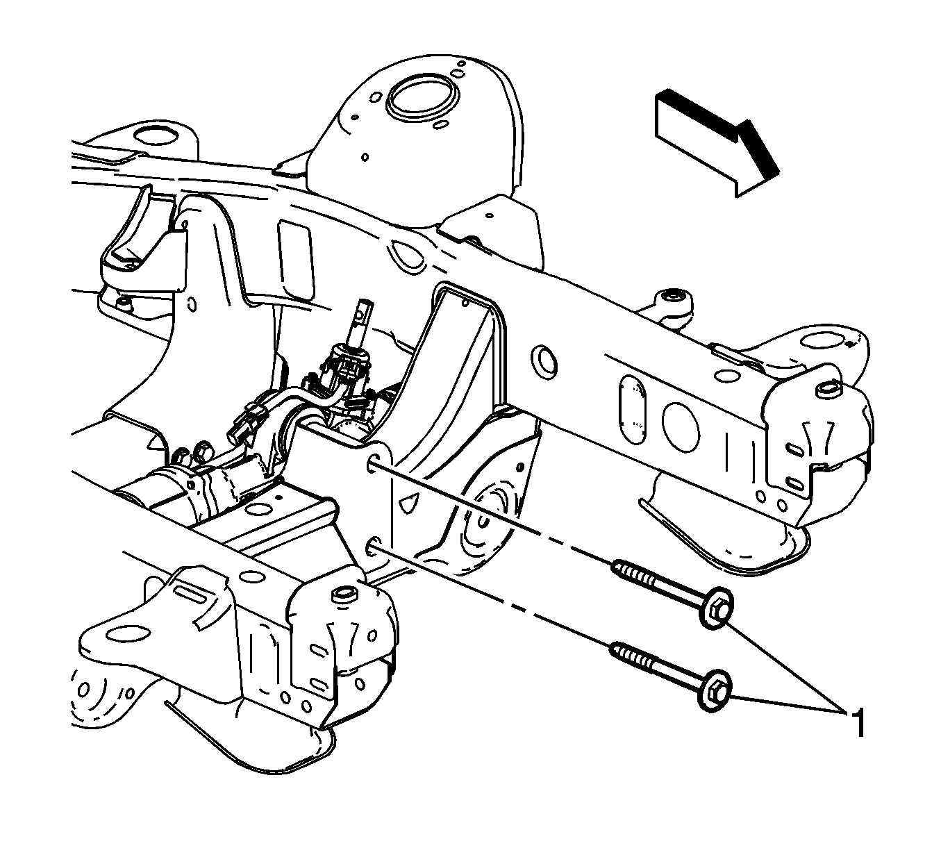
- Remove the steering gear bolts (1) from the right side of the steering gear.
- Remove the steering gear from the vehicle.
- Transfer any parts as needed.
Danger: Always perform the High Voltage Disabling procedure prior to servicing any High Voltage component or connection. Personal Protection Equipment (PPE) and proper procedures must be followed.
The High Voltage Disabling procedure will perform the following tasks:| • | Identify how to disable high voltage. |
| • | Identify how to test for the presence of high voltage. |
| • | Identify condition under which high voltage is always present and personal protection equipment (PPE) and proper procedures must be followed. |
Note: The steering gear harness is not repairable. Only replace the harness and never attempt to repair it.
Note: The wiring harness protective cover is intended to keep the wiring harness connectors contaminant free. Do not remove the protective cover from the power steering assist motor wiring harness connectors until the harness has been routed to the correct position.
Installation Procedure
- Position the steering gear in the vehicle and support it with jackstands.
- Install the steering gear bolts (1) at the right side of the steering gear.
- Install the steering gear bolts (1) to the left side of the steering gear.
- Connect the steering linkage outer tie rods (1) to the steering knuckles.
- Install the new steering linkage outer tie rod nuts.
- Connect the steering shaft coupling to the steering gear.
- Install the steering shaft coupling bolt (1) at the steering gear.
- Install the front tire and wheel assemblies. Refer to Tire and Wheel Removal and Installation.
- Perform the high voltage enabling procedure. Refer to High Voltage Enabling.
- Perform the power steering control module setup procedure. Refer to Power Steering Control Module Programming and Setup.
Caution: Refer to Fastener Caution in the Preface section.

Note: Start all steering gear bolts by hand before finalizing the torques.
Tighten
Tighten the bolts to 100 N·m (74 lb ft).

Tighten
Tighten the bolts to 200 N·m (148 lb ft).

Tighten
Tighten the nuts to 60 N·m (44 lb ft).

Tighten
Tighten the bolt to 47 N·m (35 lb ft).
