Tools Required
| • | J 36601 Pinion Shim Selector |
| • | J 29763 Static Timing Gage |
- Before assembly, lubricate the pinion bearings with axle lubricant. Use the correct fluid. Refer to Sealers, Adhesives, and Lubricants .
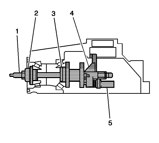
- Install the J 36601-4 or the J 36601-3 (4) to the J 36601-7 (1).
- Install the J 21777-35 for the 8.25 inch axle or the J 21777-8 for the 9.25 inch axle (3) to the J 36601-7 (1).
- Install the inner pinion bearing into the differential carrier case half.
- Insert the J 36601-7 (1) with the J 21777-35 or the J 21777-8 (3) through the inner pinion bearing and the differential carrier case half.
- Install the outer pinion bearing.
- While holding the outer pinion bearing in position, install the J 36601-5 (2), the washer, and the nut to the J 36601-7 (1).
- While holding the J 36601-7 (1) stationary with a wrench, tighten the nut on the J 36601-7 (1).
- Rotate the assembly several times in both directions in order to seat the pinion bearings.
- While holding the J 36601-4 or the J 36601-3 (4) stationary, measure the rotating torque of the J 36601 using an inch-pound torque wrench.
- If the torque is less than 1.0 N·m (10 lb in), continue to tighten the nut on the J 36601-7 until a rotating torque of 1.1-2.3 N·m (10-20 lb in) is obtained.
- Install the adjustment screw and the lock nut of the J 29763 (2) to the J 36601-4 or the J 36601-3.
- Install the J 29763 to the adjustment screw and lock nut assembly.
- Place the contact pad of the J 36601-4 or to the J 36601-3 into the differential side bearing bore.
- Adjust the J 29763 to the differential bearing bore by doing the following:
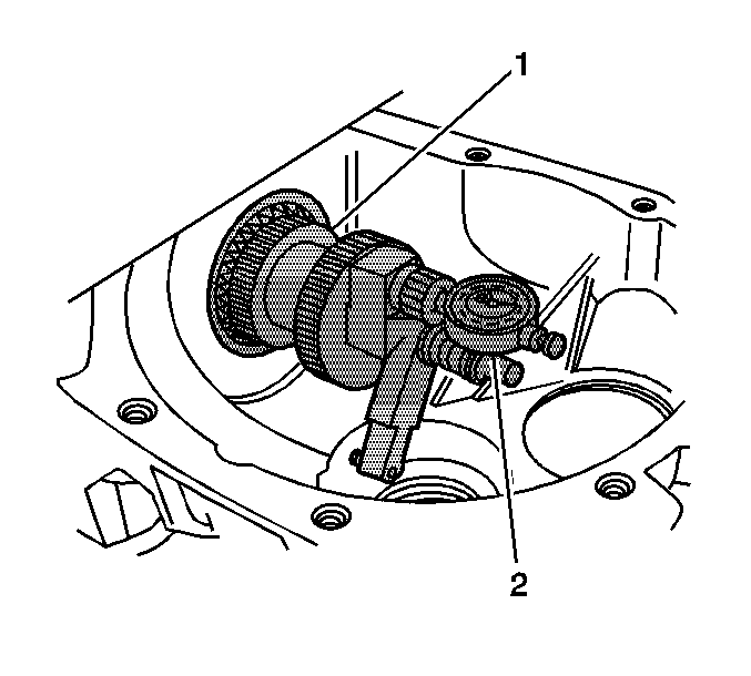
- Rotate the J 36601-4 or the J 36601-3 (1) back and forth until the needle of the J 29763 (2) indicates the lowest point in the differential side bearing bore.
- At the lowest point of deflection, move the housing of the J 29763 until the needle indicates ZERO.
- Move the J 36601-4 or the J 36601-3 back and forth again to verify the zero setting. Adjust the housing of the J 29763 as necessary to set the needle to ZERO.
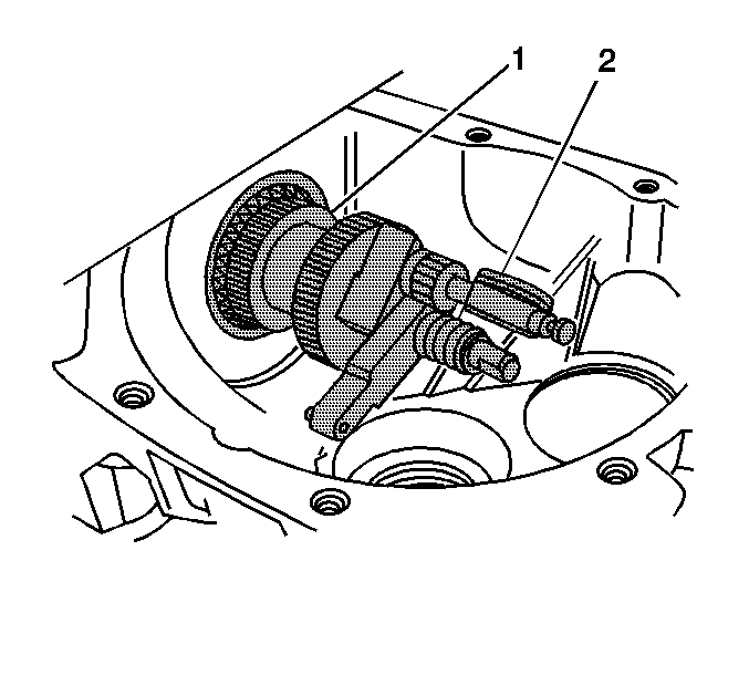
- After the ZERO setting is obtained and verified, grasp the J 36601-4 or the J 36601-3 (1) by the flats and move the J 36601-4 or the J 36601-3 out of the differential side bearing bore.
- The value indicated on the J 29763 (2) is the thickness of the shim needed in order to set the depth of the pinion.
- Select the shim that indicates the correct thickness. Measure the shim with a micrometer in order to verify that the thickness is correct.
- Remove the pinion depth setting tools.
- Remove the pinion bearings.
- Install the pinion shim between the drive pinion and the inner pinion bearing and assemble the differential carrier. Refer to Differential Carrier Assembly Assemble .
Important: Make sure all of the tools, the pinion bearings, and the pinion bearing cups are clean before proceeding.

Important: The J 36601 uses two different measuring arms to measure the pinion depth. The J 36601-4 is used to measure the pinion depth for the 8.25 inch axle and the J 36601-3 is used to measure the pinion depth for the 9.25 inch axle.
Important: Each end of the J 36601-5 is sized specifically for the 8.25 inch or the 9.25 inch outer pinion bearing. Ensure the correct end is being used when installing the J 36601-5 into the outer pinion bearing.
Notice: Refer to Fastener Notice in the Preface section.
Tighten
Tighten the nut until all of the end play is removed from the J 36601
.
Specification
The rotating torque of the J 36601
should be between 1.1-2.3 N·m (10-20 lb in).

Tighten the lock nut to hold the J 29763 in place.
Important: The left side differential bearing adjuster assembly on the 9.25 inch axle must be removed prior to placing the J 36601-3 in the differential side bearing bore.
| 15.1. | Loosen the lock nut on the J 29763 . |
| 15.2. | Place the contact pad of the J 36601-4 or the J 36601-3 onto the differential side bearing bore. |
| 15.3. | With the contact pad of the J 36601-4 or the J 36601-3 touching the differential side bearing bore, push down on the J 29763 until the needle of the J 29763 has turned 3/4 of a turn clockwise. |
| 15.4. | Tighten the lock nut of the J 29763 . |

Important: The unit of measurement for the J 29763 is in hundredths of a millimeter.
Differential pinion gear shims are available in the following sizes:
8.25 Inch Axle | 9.25 Inch Axle |
|---|---|
0.508 mm (0.020 in) | 0.5131 mm (0.0202 in) |
0.533 mm (0.021 in) | 0.5395 mm (0.0212 in) |
0.559 mm (0.022 in) | 0.5639 mm (0.0222 in) |
0.584 mm (0.023 in) | 0.5893 mm (0.0232 in) |
0.610 mm (0.024 in) | 0.6147 mm (0.0242 in) |
0.635 mm (0.025 in) | 0.6401 mm (0.0252 in) |
0.660 mm (0.026 in) | 0.6655 mm (0.0262 in) |
0.686 mm (0.027 in) | 0.6909 mm (0.0272 in) |
0.711 mm (0.028 in) | 0.7163 mm (0.0282 in) |
0.737 mm (0.029 in) | 0.7417 mm (0.0292 in) |
0.762 mm (0.030 in) | 0.7671 mm (0.0302 in) |
0.787 mm (0.031 in) | 0.7925 mm (0.0312 in) |
0.813 mm (0.032 in) | 0.8179 mm (0.0322 in) |
0.838 mm (0.033 in) | 0.8433 mm (0.0332 in) |
0.864 mm (0.034 in) | 0.8687 mm (0.0342 in) |
0.889 mm (0.035 in) | 0.8941 mm (0.0352 in) |
0.914 mm (0.036 in) | 0.9195 mm (0.0362 in) |
0.940 mm (0.037 in) | 0.9449 mm (0.0372 in) |
0.965 mm (0.038 in) | - |
0.991 mm (0.039 in) | - |
1.016 mm (0.040 in) | - |
1.041 mm (0.041 in) | - |
1.067 mm (0.042 in) | - |
1.092 mm (0.043 in) | - |
1.118 mm (0.044 in) | - |
1.143 mm (0.045 in) | - |
1.168 mm (0.046 in) | - |
1.194 mm (0.047 in) | - |
1.219 mm (0.048 in) | - |
1.245 mm (0.049 in) | - |
1.270 mm (0.050 in) | - |
