For 1990-2009 cars only
Tools Required
J 25025 Guide Pins
Removal Procedure
- Raise the vehicle. Refer to Lifting and Jacking the Vehicle in General Information.
- Remove the control valve body assembly. Refer to Control Valve Body Replacement .
- Remove the 3rd and 4th clutch accumulator housing bolts (1).
- Remove the 3rd and 4th clutch accumulator housing (8).
- Remove the accumulator housing gasket (6). The accumulator housing gasket may be stuck to the spacer plate (5).
- Remove the 3rd clutch accumulator piston spring (7).
- Remove the 4th clutch accumulator piston spring (2).
- Remove the control valve body spacer plate (5).
- Remove the control valve assembly to spacer plate gasket (4) from the spacer plate (5).
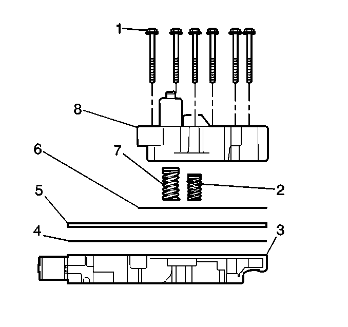
Third and Fourth Clutch Accumulator Disassembly
- Remove the 3rd clutch accumulator piston (2).
- Remove the 3rd clutch accumulator piston seals (1, 3).
- Remove the 4th clutch accumulator piston pin retainer ring (5).
- Remove the 4th clutch accumulator piston (4) and pin (2) from the accumulator housing (1).
- Remove the 4th clutch accumulator piston pin (2) from the accumulator housing (1).
- Remove the 4th clutch accumulator piston seal (3) from the accumulator housing (1).
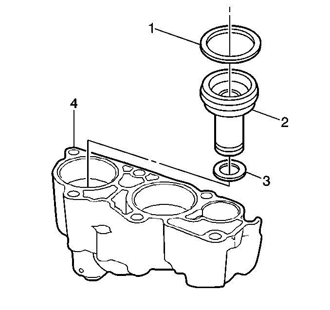
Important: Apply low pressure compressed air to the hole at the top of the accumulator housing to assist with the piston removal.
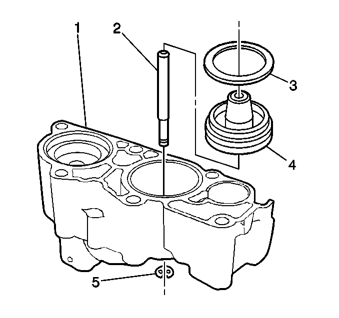
Third and Fourth Clutch Accumulator Assembly
- Install the 3rd clutch accumulator piston inner (3) and outer (1) seals. Lubricate the 3rd clutch accumulator piston seals (1, 3) with DEXRON® VI automatic transmission fluid.
- Install the 3rd clutch accumulator piston (2).
- Install the 4th clutch accumulator piston seal (3). Lubricate the 4th clutch accumulator piston seal (3) with DEXRON® III automatic transmission fluid.
- Assemble the 4th clutch accumulator piston pin (2) with the 4th clutch accumulator piston (4).
- Install the 4th clutch accumulator piston assembly into the accumulator housing (1).
- Install the 4th clutch accumulator piston pin retainer ring (5) onto the 4th clutch accumulator piston pin (2).


Installation Procedure
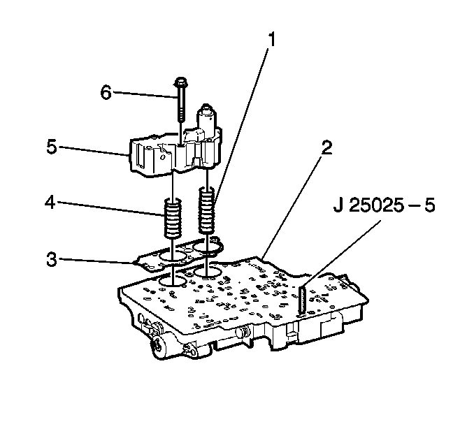
- Install the J 25025 into the control valve body bolt hole where the manual shaft detent roller and spring assembly is mounted.
- Install the control valve body gasket (2) onto the accumulator housing (1).
- Install the control valve body spacer plate (3) onto the valve body gasket (2).
- Install the third and fourth clutch accumulator housing gasket (3).
- Install the third clutch accumulator piston spring (1). This spring is the longer of the two springs.
- Install the fourth clutch accumulator piston spring (4).
- Install the third and fourth clutch accumulator housing assembly (5) onto the control valve body assembly (2).
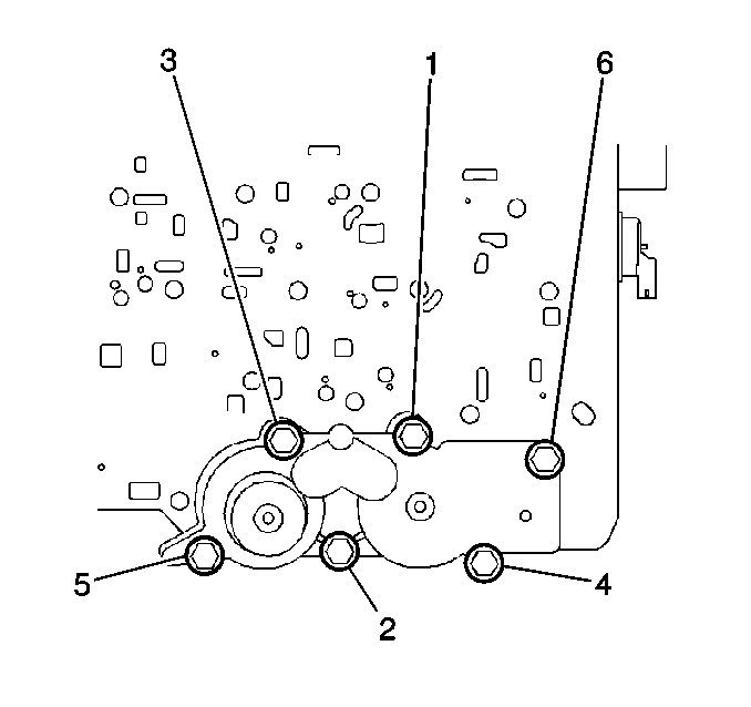
- Install the six accumulator housing bolts (6). Start the bolts finger tight and work towards the opposite end.
- Tighten the accumulator housing bolts sequentially in the order shown.
- Remove the J 25025-5.
- Install the control valve body assembly. Refer to Control Valve Body Replacement .
- Lower the vehicle.
- Fill the transmission to the proper level with approved fluid.
- Reset the TAP values. Refer to Adapt Function .
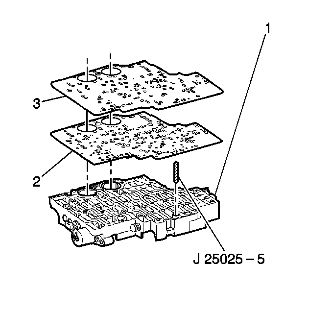
Notice: Refer to Fastener Notice in the Preface section.
Tighten
Tighten the accumulator housing bolts to 11 N·m (97 lb in).
Important: It is recommended that transmission adaptive pressure (TAP) information be reset.
Resetting the TAP values using a scan tool will erase all learned values in all cells. As a result, The ECM, PCM or TCM will need to relearn TAP values. Transmission performance may be affected as new TAP values are learned.