Noise in Engine Compartment with Air Conditioning (A/C) On, A/C System Inoperative (Install Redesigned Rear A/C Suction Hose, Replace Compressor)

| Subject: | Noise in Engine Compartment with Air Conditioning (A/C) On, A/C System Inoperative (Install Redesigned Rear A/C Suction Hose, Replace Compressor) |
| Models: | 2000-2001 Chevrolet and GMC C/K Utility Models |
| Built Prior to October 10, 2000 |
| With Auxiliary Rear A/C (RPO C69) |
This bulletin is being revised to add additional procedure information. Please discard Corporate Bulletin Number 01-01-39-002A (Section 01 -- HVAC).
Condition
Some customers may comment on excessive noise from the engine compartment with the A/C on. Some customers also may comment that the A/C system is inoperative.
Cause
Under certain driving conditions, the A/C compressor may be starved of oil.
Correction
Important: Do NOT use Rear Auxiliary A/C Line P/Ns 15065471 and 15065472.
Important:
Flushing the A/C System After Catastrophic Compressor Failure
• A/C system flushing should NOT be routinely performed when a system
failure is encountered. System flushing takes a considerable amount of time
to perform and is NOT necessary on most system failures. System flushing requires
prior authorization by the GM Area Service Manager (in Canada, the District
Service Manager) and should be performed only when any one of the following
conditions is found. • Desiccant bag failure • Gross overcharge of PAG oil • Refrigerant contamination • Contaminated PAG oil • Catastrophic compressor failure causing oil contamination • A/C system flushing will remove some of the metal particles during a
flush, but flushing is not completely effective in removing all metallic debris.
System flushing should not be considered if removal of metallic debris is
the only objective. GM Service Operations continues to recommend the use of
LIQUID LINE FILTERS to control this type of system contamination and avoid
repeat failures. • A warm engine compartment or higher ambient temperatures speed the refrigerant
recovery time during the A/C flush procedure. Whenever possible, warm the
engine prior to system flushing.
Front/Rear (Dual Circuit) A/C Systems
Important: Each circuit of a front/rear A/C system must be flushed separately. Flow to one circuit must be blocked with the use of a blocked orifice tube or blocked TXV. The front circuit should always be flushed first.
Front Circuit
- Recover the system refrigerant.
- Remove the expansion device (TXV or orifice tube) from the front circuit.
- Re-connect the A/C lines with the orifice tube removed or install the appropriate non-blocked (open) TXV Adapter from kit J 45268.
- Cut the orifice tube frame and screen.
- Remove enough of the frame and screen to access the end of the orifice tube.
- Seal the tube by pinching off the end of the orifice tube.
- Remove the expansion device (TXV or orifice tube) from the rear circuit and install a plugged expansion device (TXV or orifice tube) into the rear circuit.
- Remove the A/C compressor. Refer to the service procedure below.
- Install the appropriate A/C compressor hose assembly flush adapter(s) from kit J 45268.
- Configure the flush adapter and hose for either a forward flush or reverse flush. Refer to the Flushing Configuration below.
- Perform the flush of the front system by following the instructions supplied with the J 43600 ACR 2000.
- Replace the plugged expansion device (TXV or orifice tube) in the rear circuit with an open expansion device (TXV or orifice tube).
- Replace the open expansion device (TXV or orifice tube) in the front circuit with a plugged expansion device (TXV or orifice tube) .
- Flush the rear system by following the instructions supplied with the J 43600 ACR 2000.
Important: A blocked orifice tube is not supplied with the J 45268 Adapter
kit. A blocked orifice can be made using the following steps:
Flushing Configuration - Forward Flush
Forward flushing (the same flow as normal system operation) is recommended for contaminated refrigerant or PAG oil.
- Connect the flush filter adapter J 45268-1 to the suction port of the A/C compressor hose assembly flush adapter.
- Connect the blue hose from the J 43600 ACR 2000 to the J 45268-1 flush filter adapter.
- Connect the red hose from the J 43600 ACR 2000 to the discharge port of the A/C compressor hose assembly flush adapter.
- Follow the instructions supplied with the J 43600 ACR 2000 and flush the A/C system.
Important:
• Install a new filter inside the J 45268-1 for every flush. Service
the filter with P/N 5651802 (in Canada, use P/N 729832). Remove
and discard the check valve filter from the filter. • Always close the valve on the J 43600 ACR 2000 external
refrigerant tank before starting the flush process.
Flushing Configuration - Reverse Flush
Reverse flushing (the opposite flow of normal operation) is recommended for desiccant bag failure. Always replace the accumulator after the reverse flushing procedure is complete.
- Connect the J 45268-1 flush filter adapter to the discharge port of the A/C compressor hose assembly flush adapter.
- Connect the blue hose from the J 45268-1 flush filter adapter.
- Connect the red hose to the suction port of the A/C compressor hose assembly flush adapter.
- Follow the instructions supplied with the J 43600 ACR 2000 and flush the A/C system.
Important:
• Install a new filter inside the J 45268-1 for every flush. Service
the filter with P/N 5651802 (in Canada, use P/N 729832). Remove
and discard the check valve from the filter. • Always close the valve on the J 43600 external refrigerant tank
before starting the flush process.
Important: Refer to Corporate Service Bulletin Number 01-01-38-006A (SI 2000 Document ID #803991) for additional flushing information.
Service Procedure
Follow the service procedure below to eliminate additional compressor failures.
- Open the hood.
- Install fender covers.
- Disconnect the negative battery cable from the battery.
- Recover the refrigerant. Refer to the Refrigerant Recovery and Recharging procedure in the Service Manual (SI 2000 Document ID #291142).
- Replace the accumulator (3) with P/N 1132781. Refer to the Accumulator Replacement procedure in the Service Manual (SI 2000 Document ID #542037).
- Replace the expansion (orifice) tube (1) with P/N 03096068. Refer to the Expansion (Orifice) Tube Replacement procedure in the Service Manual (SI 2000 Document ID #536021).
- Replace the A/C compressor (2) with P/N 15081861. Refer to the Compressor Replacement LR4, LM7, LQ4, L18 w/Denso procedure in the Service Manual (SI 2000 Document ID #448700).
- Install the new suction hose, P/N 15065473, to the compressor (2) and to the accumulator. Refer to the Suction Hose Replacement LR4, LM7, LQ4, L18 w/Denso procedure in the Service Manual (SI 2000 Document ID #628200).
- Remove the retainer from the evaporator tube (2) to the air cleaner support bracket.
- Measure 152 mm (6 in) in front of the Y in the evaporator tube (2) and mark.
- Using a tubing cutter, cut the marked section of the evaporator tube (2).
- Remove the burrs from the evaporator tube (2).
- Remove the nuts (4), the ferrules (3), and the O-rings (2) from the A/C refrigerant filter (1).
- Push the nuts (4) and ferrules (3) over each of the evaporator tube halves.
- Install the ferrules (3) with the small end toward the nut (4).
- Install the A/C refrigerant filter (3), P/N 52474433, to the evaporator tube (2) with the flow arrow pointing towards the evaporator.
- While holding the evaporator tube in the A/C refrigerant filter (1), tighten the nuts (4) to the A/C refrigerant filter (1).
- Remove the nuts (4) from the A/C refrigerant filter (1).
- Coat the O-rings (2) with 525 viscosity Mineral oil, P/N 5416939 (in Canada, use P/N 10953496).
- Install the O-rings (2) to the evaporator tube halves.
- Install the nuts (4) to the A/C refrigerant filter (1).
- Install the retainer to the evaporator tube to air cleaner support bracket.
- Raise the vehicle and locate the rear A/C suction line on the right side pinch weld.
- Using a tubing cutter, cut the marked section of the rear A/C suction line and discard the front section of the line.
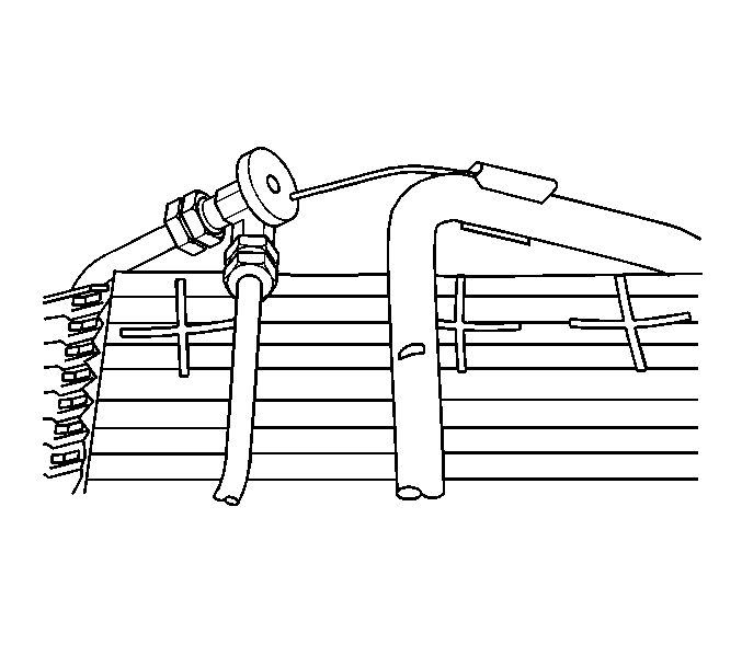
- Splice in the new front section of rear A/C suction hose, P/N 15095996, using J 41425 A/C Line Repair Kit and splice J 41425-750. Refer to the Heater and A/C Pipe Repair - Auxiliary procedure in the Service Manual (SI 2000 Document ID #594055).
- Connect the rear A/C suction line to the Y in the suction line attached to the compressor.
- Install the wheelhouse panel to the wheelhouse. Refer to the Wheelhouse Panel Replacement procedure in the Service Manual (SI 2000 Document ID #449783).
- Replace the rear thermo expansion valve with P/N 52491670. Refer to the Thermal Expansion Valve Replacement - Auxiliary procedure in the Service Manual (SI 2000 Document ID #594045).
- Add A/C system Fluorescent Tracer Dye to the A/C system, P/N 12346303 (in Canada, use P/N 10953458). Refer to the Leak Testing procedure in the Service Manual (SI 2000 Document ID #4486920).
- Add the A/C system dye notification label to the upper radiator support.
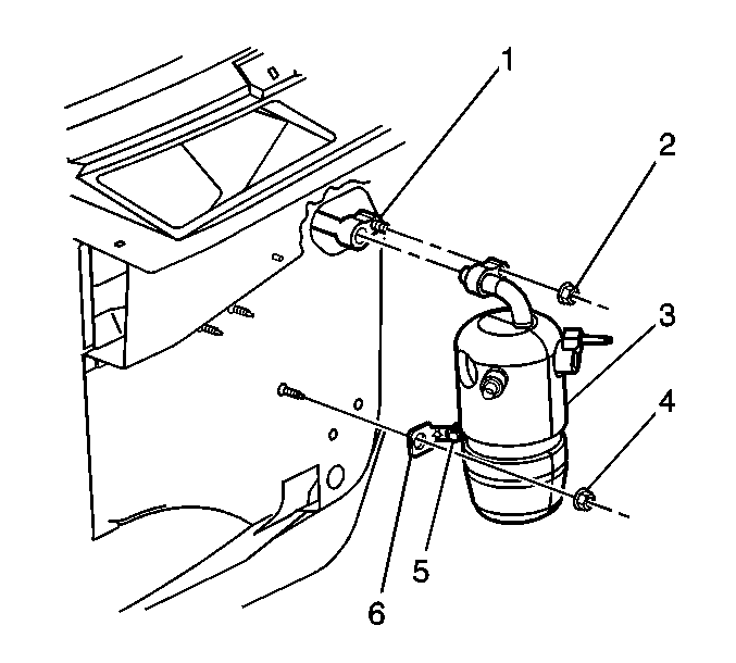
Important:
• Add 60 ml (2 oz.) of PAG oil, P/N 12345923
(in Canada, use P/N 10953486), plus the equal amount of oil drained
from the accumulator. • Do not install the old suction hoses from the compressor and the rear
A/C line to the new accumulator (3).
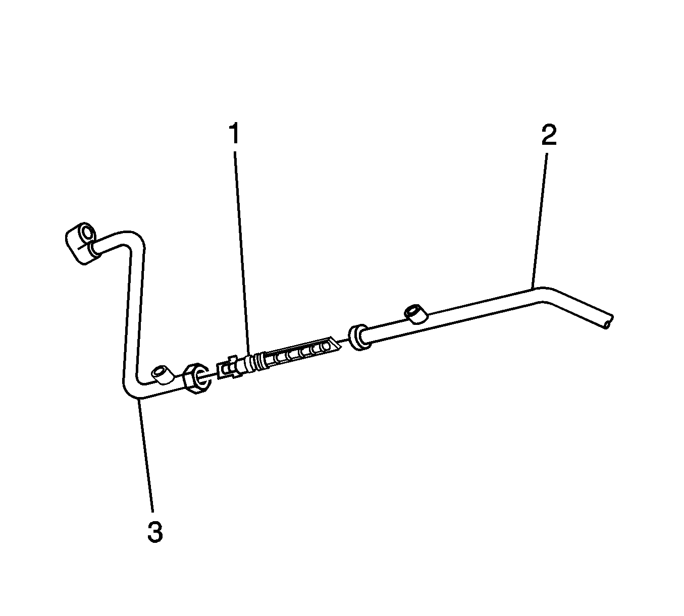
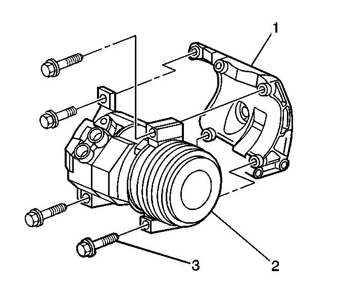
Important:
• Do not install the old suction hose to the new compressor. • Do not reinstall the wheelhouse panel to the wheelhouse at this time. • Drain and measure as much of the oil as possible from the removed compressor. • Drain the oil from both the suction and discharge ports of the removed
A/C compressor into a clean container. • Measure and record the amount of oil drained from the removed A/C compressor.
This measurement will be used during installation of the replacement A/C compressor. • If more than 60 ml (2 oz.) of PAG oil was drained from
the compressor, add the equal amount of PAG oil that was drained from the
old compressor. • If less than 60 ml (2 oz.) of PAG oil was drained from
the compressor, add 60 ml (2 oz.) of PAG oil to the new compressor.
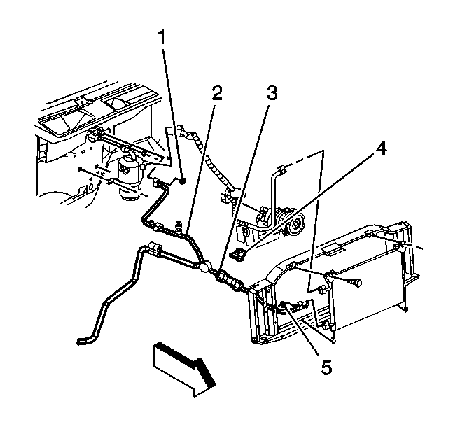
Important:
• Denso DOES NOT RECOMMEND the use of SUCTION SCREEN FILTERS with Denso
compressors. • Do not allow metal burrs to enter the evaporator tube (2) during
cutting or when removing the burrs. • When you section the A/C lines, ensure that the correct minimum length
remains in the straight part of the line on both sides of the filter.
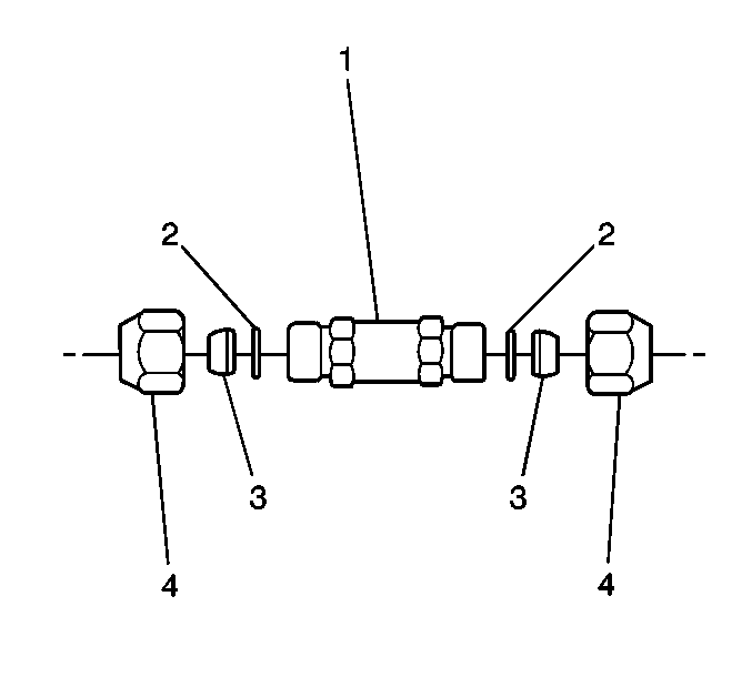
Important: Do not install the O-rings (2) in this step.
Tighten
Tighten the nuts to 15 N·m (11 lb ft).
Tighten
Tighten the nuts to 15 N·m (11 lb ft).
Important:
• Measure 152 mm (6 in) rear of first rear A/C line retaining
clip and mark the suction line. • Do not allow metal burrs to enter the rear A/C suction line. • When you section the A/C lines, ensure that the correct minimum length
remains in the straight section of the line on both sides of the splice.
Tighten
Tighten the nut to 16 N·m (12 lb ft).
Important:
• Vehicles that have had multiple compressor failures due to oil starvation
should replace the condenser. • Do not replace the condenser if the compressor has not been replaced
prior to this repair.
Condenser Replacement
- Remove the upper radiator close out panel.
- Remove both headlamp assemblies.
- Remove the grille.
- Remove both turn signal lamp assemblies.
- Remove the six bolts retaining the radiator support brace and position the brace so that the condenser can be removed.
- Remove the condenser.
- Install a new condenser, P/N 52475996, and add 30 ml (1 oz) of PAG oil, P/N 12345923 (in Canada, use P/N 10953486).
- Install the six bolts retaining the radiator support brace.
- Install the turn signal lamps.
- Install the grille.
- Install the head lamp assemblies.
- Install the upper radiator close out panel.
- Recharge the A/C system. Refer to the Refrigerant Recovery and Recharging procedure in the Service Manual (SI 2000 Document ID #291142).
- Perform the System Performance Test (Suburban/Yukon XL) procedure in the Service Manual (SI 2000 Document ID #631165).
Tighten
| • | Tighten the suction and discharge line to 16 N·m (12 lb ft). |
| • | Tighten the condenser mounting bolts to 2.4 N·m (21 lb in). |
Tighten
Tighten the radiator brace bolts to 9 N·m (80 lb in).
Tighten
Tighten the grille screw to 9 N·m (75 lb in).
Parts Information
Part Number | Description |
|---|---|
01132781 | Accumulator Asm. - A/C |
03096068 | Orifice Asm. - A/C |
12345923 (In Canada use 10953486) | Oil-PAG A/C Compressor |
12346303 (In Canada use 10953458) | Dye - A/C System |
12356150 (In Canada use 12345922 | Refrigerant - A/C (R134a) |
15095996 | Hose Asm.- Aux. A/C Suction. |
15065473 | Hose Asm.- A/C Accum |
15081861 | Compressor Asm.- A/C |
52474433 | Filter Asm., A/C Refrig (inline w/o orifice) |
52475996 | Condenser Asm. - A/C |
52491670 | Valve Kit, Aux A/C Evap Therm Expn |
Parts are currently available from GMSPO.
Warranty Information
For vehicles repaired under warranty, use:
Labor Operation | Description | Labor Time |
|---|---|---|
D4706 | A/C System- Repair and Replace with rear A/C (C69) | 4.9 hrs |
D3140 | Condenser-Replace | 0.9 hr |
GM has not established a specific labor operation for system flushing. When system flushing is necessary during the warranty period, submit additional labor hours with the labor operation used for the system repair. | ||
