GM Service Manual Online
For 1990-2009 cars only

Customer Satisfaction - Inoperative Wireless Headphones and Remote Control/Missing Rear Audio/Video Jacks(EXPORT ONLY)

Subject:07152 -- Inoperative Wireless Headphones and Remote Control/Missing Rear Audio/Video Jacks (EXPORT ONLY)

Models:2007 Chevrolet Suburban 1500/2500 Series
2007-2008 Chevrolet Tahoe 1500 Series
2008 Chevrolet Suburban 1500 Series
2007-2008 GMC Yukon 1500 Series
2007 GMC Yukon XL 1500/2500 Series
2008 GMC Yukon XL 1500 Series
With Export Radio Frequency (RPO UL8), Rear Seat Entertainment System (RPO U42) and CD/DVD Radio (RPO UVA) or Navigation Radio (RPO UVB)


Condition

On some 2007 Chevrolet Tahoe and Suburban; GMC Yukon and Yukon XL vehicles, the wireless headphones and remote control included with the rear seat entertainment system (RPO U42) may be inoperative. These vehicles were built without the correct wiring required to operate these units. Vehicles with the CD/DVD (non-navigation) radio are also missing audio/video jacks in the console rear trim plate.

Correction

Dealers are to install a jumper wiring harness specific to the type of radio, and on vehicles with the CD/DVD radio, dealers are to install a new console rear trim plate that contains audio/video jacks.

Vehicles Involved

Involved are 2007 Chevrolet Tahoe and Suburban; and GMC Yukon and Yukon XL vehicles with CD/DVD radio (RPO UVA) or Navigation Radio (RPO UVB) and built within these VIN breakpoints:

Year

Division

Model

From

Through

2007

Chevrolet

Suburban

7G270761

7G304560

7J312320

7J374568

2008

Chevrolet

Suburban (one vehicle)

8J100038

8J100038

2007

Chevrolet

Tahoe

7J299350

7J380044

7R345799

7R413319

2008

Chevrolet

Tahoe (one vehicle)

8J100013

8J100013

2007

GMC

Yukon

7J309350

7J380024

2008

GMC

Yukon

8J100017

8J100019

2007

GMC

Yukon XL

7J309543

7J380038

7R345883

7R413854

2008

GMC

Yukon XL (one vehicle)

8J100046

8J100046

Important: Dealers are to confirm vehicle eligibility prior to beginning repairs by using the GM Vehicle Inquiry System (GMVIS). Not all vehicles within the above breakpoints may be involved.

For dealers with involved vehicles, a listing with involved vehicles containing the complete vehicle identification number, customer name, and address information has been prepared and will be provided directly to dealers. Dealers will not have a report available if they have no involved vehicles currently assigned.

The listing may contain customer names and addresses obtained from Motor Vehicle Registration Records. The use of such motor vehicle registration data for any purpose other than follow-up necessary to complete this program is a violation of law in several countries. Accordingly, you are urged to limit the use of this report to the follow-up necessary to complete this program.

Parts Information

Parts required to complete this program are to be obtained from General Motors Service and Parts Operations (GMSPO). Please refer to your "involved vehicles listing" before ordering parts. Normal orders should be placed on a DRO = Daily Replenishment Order. In an emergency situation, parts should be ordered on a CSO = Customer Special Order.

Part Number

Description

Qty/ Vehicle

25896361

Harness, F/Flr Cnsl Wrg (UVA - Non-Navigation Radio)

1

25896362

Harness, F/Flr Cnsl Wrg (UVB - Navigation Radio)

1

25895905

Bezel, F/Flr Cnsl Compt (UVA - Non-Navigation Radio)

1

Service Procedure

The service procedure in this bulletin provides repair instructions for non-navigation radio, DVD and Mid East radio frequencies (RPO UVA U42 UL8), and navigation radio, DVD, and Mid East radio frequencies (RPO UVB U42 UL8). Performing the service repair procedure in this bulletin will restore headphone and remote control function for non-navigation and navigation radios with DVD. Instructions for installing functional audio video jacks on vehicles equipped with non-navigation radios with DVD are provided as well.

Required Tools and Materials

Use the tools referenced in this section, or equivalent, to complete the service procedure in this bulletin.
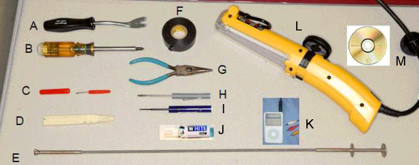

Object Number: 1977806  Size: MF
(a)Attachment Clip Removal Tool
(b)Phillips Screw Driver
(c)Seam Ripper
(d)Trim Removal Tool
(e)Flexible Fish Tool
(f)Electrical Tape
(g)Slim Nose Pliers
(h)Standard Screw Driver
(i)Terminal Pick
(j)White Marker
(k)A/V Player Device with A/C Cable
(l)Portable Light
(m)DVD Disc (Pre-Recorded)

Preparation Instructions

Before performing the service procedure in this bulletin, carefully read the information below.

    • Identify which system repair is required: UVA U42 UL8 or UVB U42 UL8.
    • Select the correct harness to perform the repair procedure:
       - 25896361 for UVA
       - 25896362 for UVB
    • Do not start the vehicle unless it is in an approved designated area.
    • Ensure the vehicle is the RUN mode during system testing to avoid battery discharge.
    • Perform the service procedure with the doors closed to avoid battery discharge.
    • Check audio/DVD system in the vehicle before performing the repair procedure. Ensure there are no other conditions that will affect the performance of the audio/DVD system.
    • Test the audio/DVD system immediately after the harness repair. Do not assemble the console before inspecting the audio/DVD system.
    • Test the audio/DVD system after installing the console to ensure the repair harness is not pinched, cut, or chaffed.

Radio System (Pre Rear Seat Audio (RSA) Trim Plate Removal/Installation)

  1. Turn the vehicle ignition to the RUN position, but do not start the engine.
  2. Turn radio ON and check the function of all of the speakers.
  3. If the vehicle is equipped with the UVB radio system, check the navigation function (e.g., map display, etc).

  4. Insert the DVD disc (tool M) into the DVD player.
  5. 3.1. Check for DVD function at the DVD display (UVA).
    3.2. Check for DVD function at Navigation Radio and DVD display for (UVB). The vehicle must be in the PARK (P) position for the DVD with Navigation radio.
    3.3. Check for DVD sound at all speaker locations.

Jumper Harness Installation


    Object Number: 1977810  Size: SH

    Important: Use a portable light to aid in the removal of the console cup holder, if required.

  1. Remove the cup holder from the console.
  2. 1.1. Carefully lift cup holder trim upward with trim removal tool (tool D).
    1.2. Pull cup holder rearward to release cup holder away from console insert tabs (1).
    1.3. Store the cup holder trim in a safe location.

    Object Number: 1977830  Size: SH
  3. Disconnect the 40-way in-line connection (1).
  4. 2.1. Use the attachment clip removal tool (tool A) to pry the clips (2) out from behind the 40-way connector and console assembly.

    Object Number: 1977834  Size: SH
    2.2. Squeeze the release locks (3) and pull the connector lever back.

    Object Number: 1977837  Size: SH
    2.3. Disconnect the 40-way connector by pulling the male and female connector apart.
  5. Remove the rear seat audio (RSA) trim plate.
  6. 3.1. Raise the console arm to access the RSA removal tabs.

    Object Number: 1977841  Size: SH
    3.2. Using trim removal tool (tool D), press down and rearward to release the RSA removal tabs. The tabs are located on the right and left side of the arm rest hinge.

    Object Number: 1977845  Size: SH
    3.3. Disconnect the 5 J-clip retainers that secure the RSA trim plate by pulling the RSA trim plate away from the console as shown in the illustration

    Important: Replacing the RSA trim plate with a new RSA trim plate is only required for vehicles equipped with the UVA radio system. Vehicles equipped with UVB radio system proceed to Step 7.

  7. Remove the rear seat audio (RSA) trim plate.

  8. Object Number: 1977848  Size: SH
    4.1. Disengage the blue connector locks (1) for each 16-way connector on the RSA trim plate.

    Object Number: 1977853  Size: SH
    4.2. Disconnect the 16-way connectors from the RSA header.

    Object Number: 1977855  Size: SH
    4.3. Remove the power point connection from the RSA trim plate by releasing the power point connection release lock using a standard screw driver (tool H).
  9. Remove the RSA module without A/V jacks from the RSA trim plate on vehicles equipped with UVA radio system.

  10. Object Number: 1977857  Size: SH
    • Remove the 4 screws securing the RSA module to the RSA trim plate using a Phillips head screw driver (tool B).
    • Disconnect the connectors from RSA module.

    Object Number: 1977860  Size: SH
    • Separate the RSA module from the RSA trim plate. Note the RSA trim plate does not have audio/video jacks (1).
  11. Install the RSA module into the new RSA trim plate. The new RSA trim plate has audio/video jacks (2).
  12. 6.1. Attach the RSA module to the RSA trim plate with 4 screws.

            Important: The RSA module is error proofed for reassembly.

    6.2. Attach all connectors except the 16-way gray connector.

    Object Number: 1977862  Size: SH

    Object Number: 1977867  Size: SH
  13. Attach the repair harness to the flexible fish tool (tool E) and route the repair harness through the console.
  14.         Important: Do not apply tape directly to the terminals.

    7.1. Tape repair harness to flexible fish tool (tool E) at the feed-through end (1) of the tool.
       • For vehicles equipped with the UVB radio system, tape the harness end with five 0.64 female terminals to the feed-through end of the flexible fish tool (tool E).
       • For vehicles equipped with the UVA radio system, tape the harness end with the gray 16-way connector.

    Object Number: 1977869  Size: SH
    7.2. Feed the repair harness through the lower left-hand front side of the console.

    Object Number: 1977871  Size: SH
    7.3. Pull the repair harness (1) out from the lower left-hand rear side of the console.
    7.4. Connect the 8-way audio/video jack connector if the vehicle is equipped with the UVA radio system. The UVB harness will not have the 8-way connector.
  15. Install the terminals at 40-way connector (UVA and UVB radio systems).

  16. Object Number: 1977875  Size: SH
    • Cut back 50 mm (2 in) of tape on the console harness using a seam ripper (tool C). This will expose the circuits, which improves cavity access at the 40-way connector.

    Object Number: 1977879  Size: SH
    • Release the blue TPA locks using the standard screw driver (tool H).

    Object Number: 1977881  Size: SH
    • Spread the wires between the cavity rows for TPA removal.
    • Mark one TPA (1) with the white marker stick (tool J).
    • Mark the corresponding connector side (1) with the white marker stick (tool J). Do not mark the other TPA or corresponding connector side.

    Object Number: 1977882  Size: SH
    • Remove both TPAs from the connector assembly.
    • Mate the parts marked with white stick (tool J) together. Left and right TPAs have acquired specific location memory.

    Object Number: 1977884  Size: SH
    • Remove the blue PLR using the terminal pick (tool I). Release PLR locks.
    • Move the PLR outward to the pre-stage position.
    • Grab the PLR using slim nose pliers (tool G). Remove the PLR by pulling it outward or away from connector.

    Object Number: 1977885  Size: SH

       Notice: Use push, click, and tug technique to check terminal seating.

    • Use the console jumper repair drawing to identify the male terminals and circuits to indexed cavities. Plug each terminal from the rear of connector. The terminal is properly seated when an "audible click" is produced. Refer to the appropriate jumper repair drawing in this bulletin.
    • Ensure all terminals are seated to correct cavities.

    Object Number: 1977886  Size: SH
    • Align the PLR with the terminals.
    • Push the PLR inward toward the connector to the pre-stage position. The terminals will protrude through the PLR.
    • Re-install both TPAs from the connector assembly.
    • Spread the wires and align the combs to the cavities.
    • Mate the white painted parts together.
    • Mate the non-white painted parts together.

    Object Number: 1977887  Size: SH
    • Push the TPAs (1) in until the locks engage. The PLR will seat fully when the lever lock is engaged. Refer to illustration.
    • If the 16-way connector has not been removed, then remove it from RSA module. Disengage the blue lock and remove the connector.

    Object Number: 1977888  Size: SH
    • Unlock the red TPA from the gray 16-way connector using the terminal pick (tool I).
    • Slide the TPA outboard using the terminal pick (tool I).
    • Remove the TPA from the connector.

    Object Number: 1977890  Size: SH
    • Insert the female 0.64 terminals into the correct cavities by index and circuit number as designated on UVB or UVA specific drawing. Use the push, click, and tug technique to inspect the terminal seating.

    Object Number: 1977891  Size: SH
    • Re-install the TPA into the 16-way connector. Push through until seated and the lock is engaged.

    Object Number: 1977896  Size: SH
    • Reinstall the connector to the RSA module.
    • Seat the connector fully and push the blue lock to engage.

Important: Do not re-install the RSA trim plate until the radio system test has been completed. Refer to Radio System Test (Post RSA Trim Plate Installation) in this bulletin.

Radio System Test (Post RSA Trim Plate Installation)

    Important: Perform the Radio System Test (Post RSA Trim Plate Installation) twice. The first test is to verify correct installation of the repair jumper. The second test (after the RSA trim plate has been installed) is to ensure that no wires have been damaged during the trim plate installation.

  1. Check the DVD remote control function.
  2. Check the headphone operation.
  3. 2.1. Turn the red switch on the headphones to ON.
    2.2. Adjust the headphone volume to medium volume.
  4. Cycle through the RSA operation: FM, DVD, and then select AUX Video input..
  5. Using an A/V player device with an A/V cable that has audio/video jacks (tool K), connect the RSA A/V input jacks.
  6. Check for video audio signal at the DVD display (2nd Row) and at headphones.
  7. Check the operation of the heated seat switches.
  8. Check the HVAC control functionality, which requires HVAC front controls set to AUX.
  9. Tape the repair jumper to the console harness and install the RSA Trim plate. Refer to Step 9 in the Jumper Harness Installation (Continued) procedure section of this bulletin.

  10. Object Number: 1977897  Size: SH
  11. Tape the repair jumper to the console harness using the electrical tape material (tool F). Solid-tape the console harness and the repair harness together. The length of the solid-tape is about 50 mm (2 in).
  12. Install the RSA trim plate attachment clips. Replace broken or damaged clips, if required.

  13. Object Number: 1977845  Size: SH
  14. Align the 5 J-clips with the console and the RSA trim plate.
  15. Seat the RSA trim plate until an audible click sound is produced.
  16. Inspect the RSA trim plate fit. Adjust the fit if required.

  17. Object Number: 1977951  Size: SH
  18. Install the cup holder into the console. No tools are required to complete this step.
  19. 14.1. Locate the insert tabs underneath the switch bank (2).
    14.2. Align the insert tabs to the receivers and push the cup holder forward until the tabs are seated (2).
    14.3. Push down on the cup holder until the J-clips are seated (1).
  20. Perform the Radio System Test (Post RSA Trim Plate Installation) for the second time.

Object Number: 2001019  Size: FP

Object Number: 2001022  Size: FP

Claim Information

Submit a Product Claim with the information indicated below:

Repair Performed

Part Count

Part No.

Parts Allow

CC-FC

Labor Op

Labor Hours

Install Jumper Harness & Console Bezel (UVA - Non-Navigational Radio)

2

--

*

MA-96

V1643

1.1

Install Jumper Harness (UVB - Navigational Radio)

1

--

*

MA-96

V1644

0.8

* The "Parts Allowance" should be the sum total of the current GMSPO Dealer net price plus applicable Landed Cost Mark-Up for the harness, and on UVA vehicles, the bezel, needed to complete the repair.

Refer to the General Motors WINS Claims Processing Manual for details on Product Recall Claim Submission.

Customer Notification

Letters will be sent to known owners of record located within areas covered by the US National Traffic and Motor Vehicle Safety Act. For owners outside these areas, dealers should notify customers using the attached sample letter.

Dealer Program Responsibility

All unsold new vehicles in dealers' possession and subject to this program must be held and inspected/repaired per the service procedure of this program bulletin before customers take possession of these vehicles.

Dealers are to service all vehicles subject to this program at no charge to customers, regardless of mileage, age of vehicle, or ownership, from this time forward.

Customers who have recently purchased vehicles sold from your vehicle inventory, and for which there is no customer information indicated on the dealer listing, are to be contacted by the dealer. Arrangements are to be made to make the required correction according to the instructions contained in this bulletin. A copy of the customer letter is provided in this bulletin for your use in contacting customers. Program follow-up cards should not be used for this purpose, since the customer may not as yet have received the notification letter.

In summary, whenever a vehicle subject to this program enters your vehicle inventory, or is in your dealership for service in the future, you must take the steps necessary to be sure the program correction has been made before selling or releasing the vehicle.

August 2007

Dear General Motors Customer:

We have learned that the wireless headphones and remote control included with the rear seat entertainment system in some 2007 model year Chevrolet Tahoe and Suburbans, and GMC Yukon and Yukon XL vehicles may be inoperative. These vehicles were built without the correct wiring required to operate these units. Vehicles with the CD/DVD (non-navigation) radio are also missing audio/video jacks in the console rear trim plate.

Your satisfaction with your vehicle is very important to us, so we are announcing a program to correct this condition.

What We Will Do: To correct this condition, your GM dealer will install a jumper wring harness specific to the type of radio in your vehicle, and if your vehicle is equipped with a CD/DVD radio, your dealer will install a new console rear trim plate that contains audio/video jacks. This service will be performed for you at no charge.

What You Should Do: To limit any possible inconvenience, we recommend that you contact your dealer as soon as possible to schedule an appointment for this repair. By scheduling an appointment, your dealer can ensure that the necessary parts will be available on your scheduled appointment date.

We sincerely regret any inconvenience or concern that this situation may cause you. We want you to know that we will do our best, throughout your ownership experience, to ensure that your GM vehicle provides you many miles of enjoyable driving.

Scott Lawson

General Director,

Customer and Relationship Services

Enclosure

07152