- Lubricate all necessary parts with Dextron ™ III Automatic
Transmission Fluid or the equivalent.
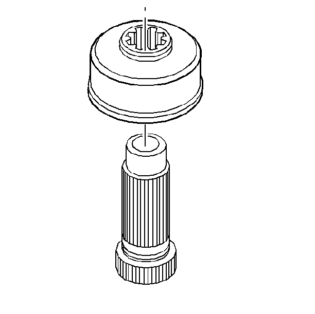
- Install the viscous clutch
onto the sun gear shaft.
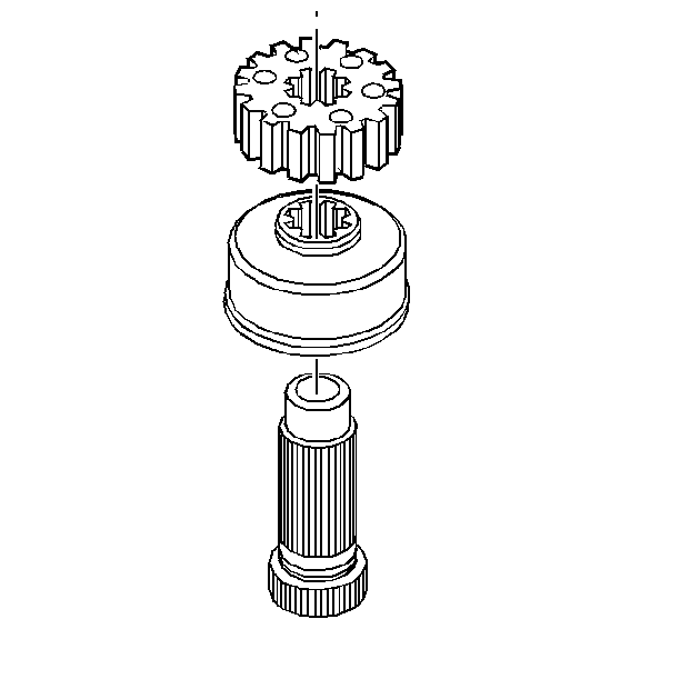
- Install the drive sprocket
onto the sun gear shaft assembly.
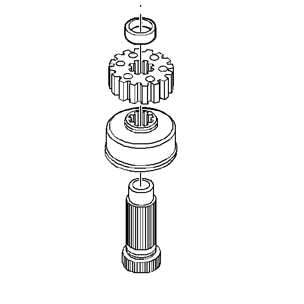
- Install the drive sprocket
spacer to the sun gear shaft assembly.
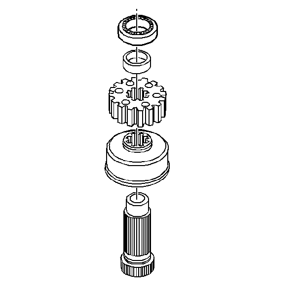
- Install the sun gear shaft
bearing to the sun gear shaft assembly.
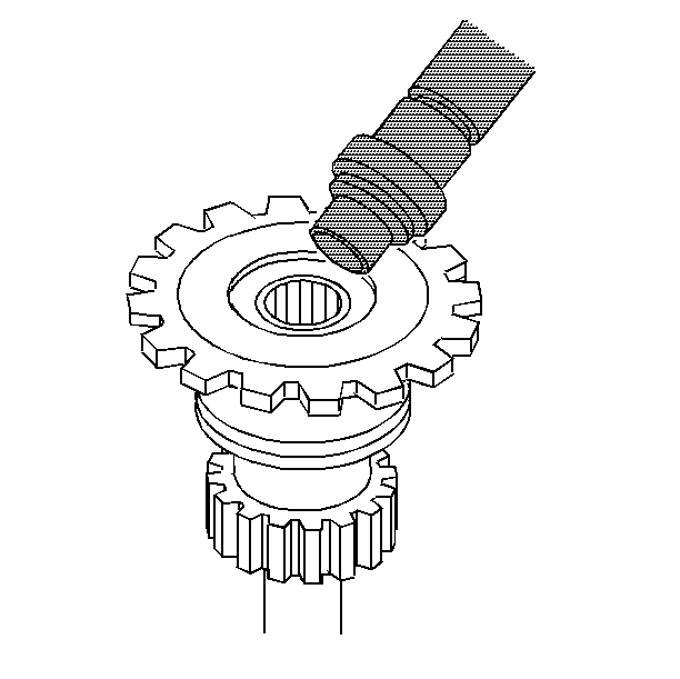
- Use the J 7079-2
and the J 38212
in order to install the input shaft pilot bushing into the
output shaft assembly.
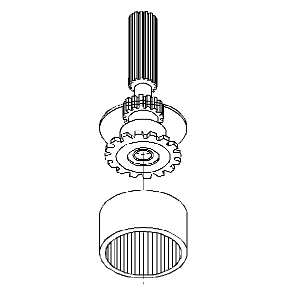
- Install the output shaft
assembly to the ring gear.
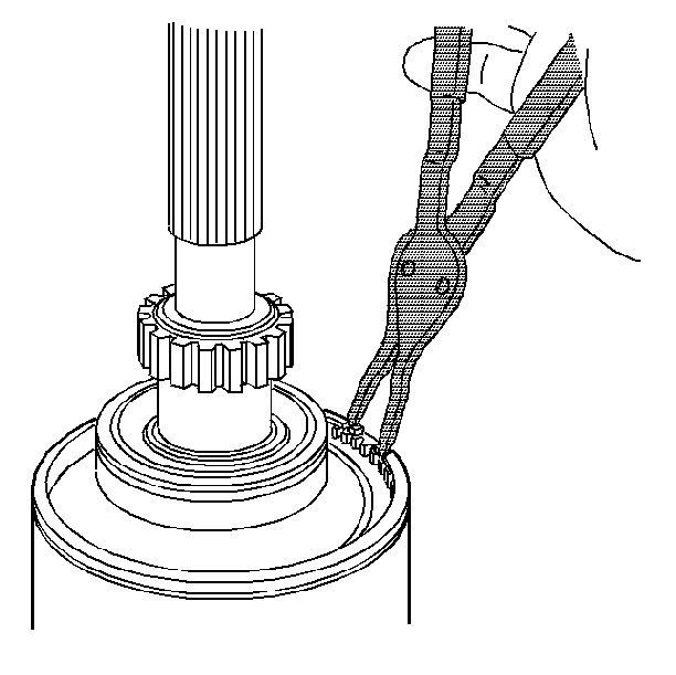
- Install the snap ring
to the ring gear.
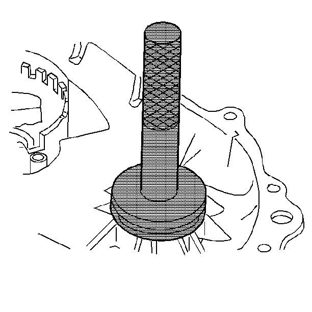
- Use the J 8092
and the J 38423
in order to install the front output shaft bearing to the
front cover.
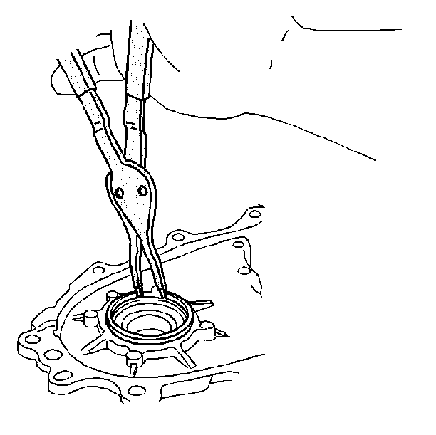
- Install the front output
shaft bearing snap ring to the front cover.
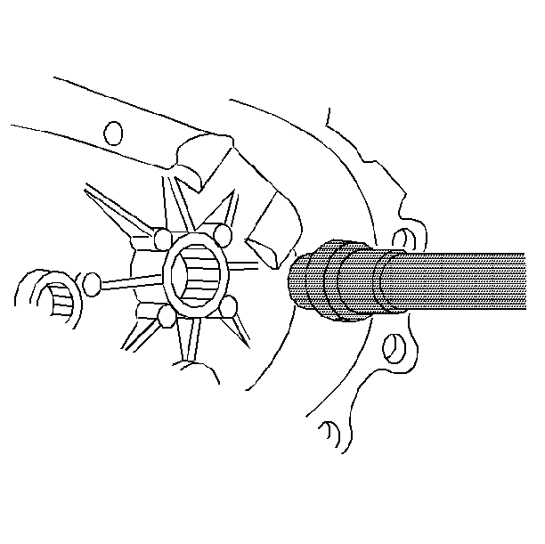
- Use the J 7079-2
and the J 38212
in order to install the bearing to the rear case half.
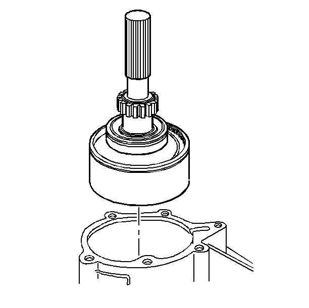
- Install the output shaft
assembly and the ring gear through the rear case half.
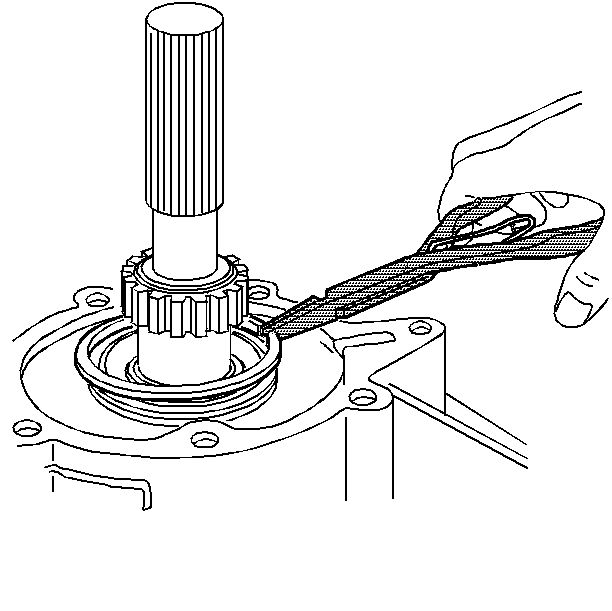
- Install the snap ring
to the output shaft bearing
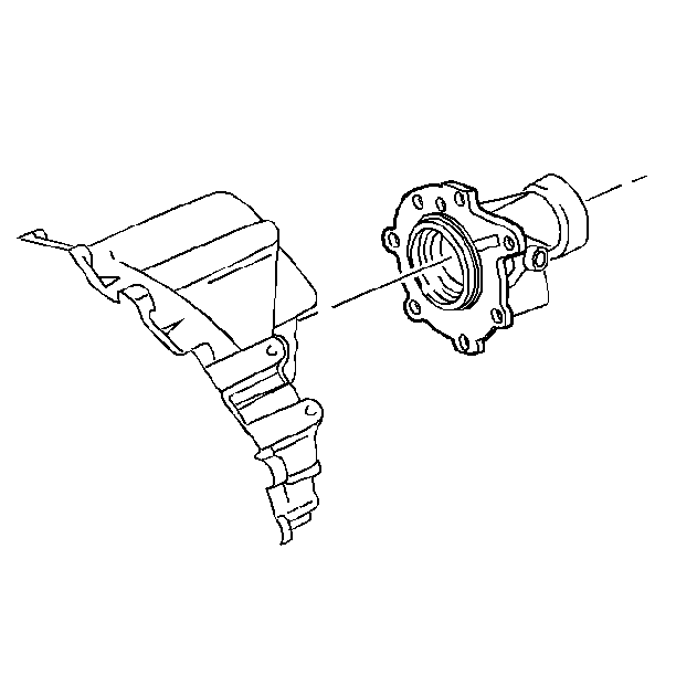
- Apply a 1/8 inch
bead of RTV sealer (GM P/N 12345739) or the equivalent to the rear extension
housing sealing surface.
- Install the rear extension housing.
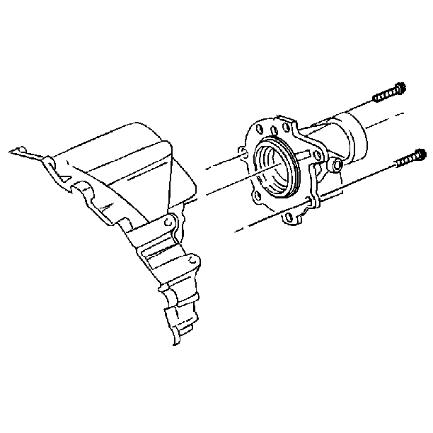
- Install the bolts to the
rear extension housing.
Tighten
Tighten the bolts to 42 N·m (30 lb ft).
Notice: Use the correct fastener in the correct location. Replacement fasteners
must be the correct part number for that application. Fasteners requiring
replacement or fasteners requiring the use of thread locking compound or sealant
are identified in the service procedure. Do not use paints, lubricants, or
corrosion inhibitors on fasteners or fastener joint surfaces unless specified.
These coatings affect fastener torque and joint clamping force and may damage
the fastener. Use the correct tightening sequence and specifications when
installing fasteners in order to avoid damage to parts and systems.
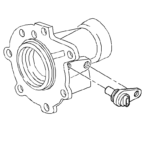
- Lubricate the vehicle
speed sensor O-ring with transmission fluid.
- Install the vehicle speed sensor.
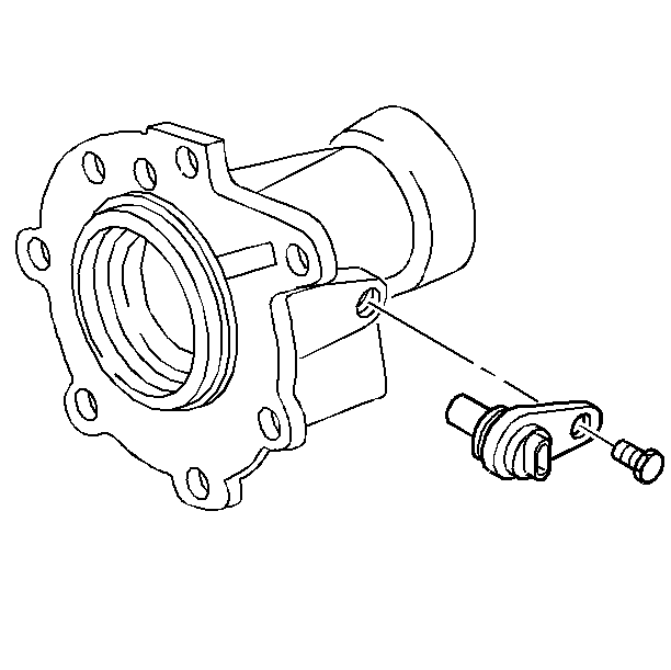
- Install the speed sensor
bolt.
Tighten
Tighten the speed sensor bolt to 16 N·m (12 lb ft).
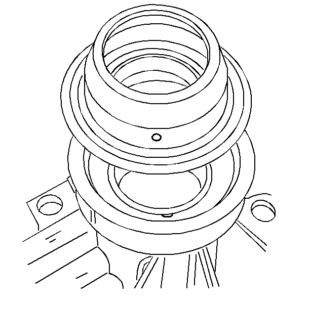
- Align the water drain
hole in the output shaft oil seal with the drain groove in the extension
housing.
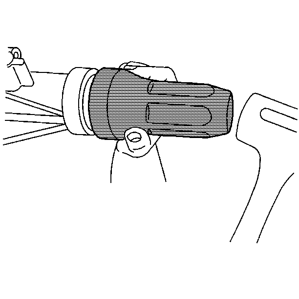
- Use the J 37668
in order to install the output shaft
seal.
- Lubricate the seal sealing lips with automatic transmission fluid.
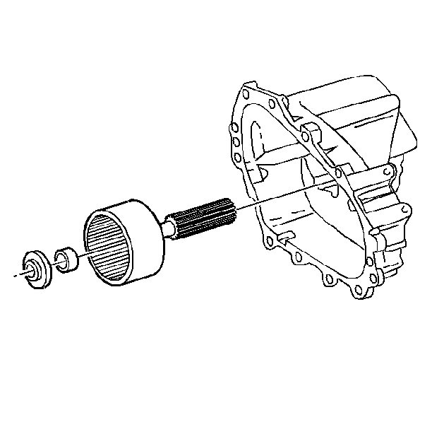
- Install the planet carrier
thrust washer to the output shaft assembly.
| • | Use petroleum jelly in order to lubricate the washer. |
| • | Align the thrust washer with the input shaft pilot bearing. |
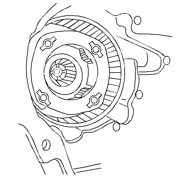
- Install the planet carrier
assembly into the ring gear.
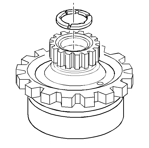
- Install the sun gear thrust
washer to the planet carrier assembly.
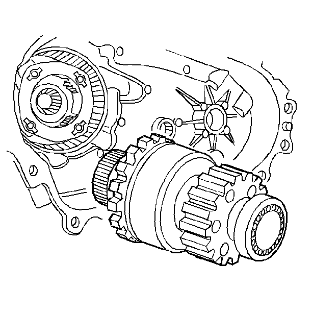
- Install the sun gear shaft
assembly into the planet carrier assembly gears. Align the viscous clutch
teeth with the ring gear spline.
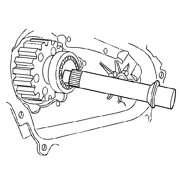
- Install the input shaft
into the input shaft pilot bearing.
| • | Align the input shaft with the sun gear shaft thrust washer. |
| • | Align the input shaft with the planet carrier thrust washer. |
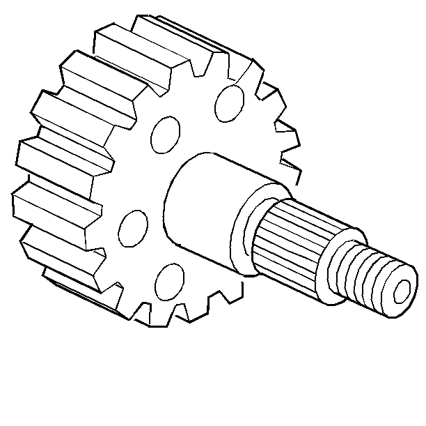
- Install the driven sprocket
onto the front output shaft. Install the driven sprocket with the letter
E facing down.
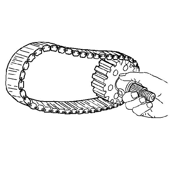
- Install the drive chain
onto the driven sprocket and front output shaft.
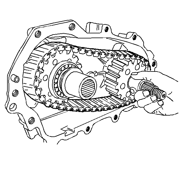
- Install the drive chain
onto the drive sprocket and install the front output shaft into the output
shaft rear bearing.
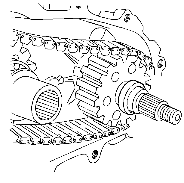
- Install the spacer onto
the front output shaft.
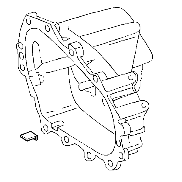
- Install the magnet.
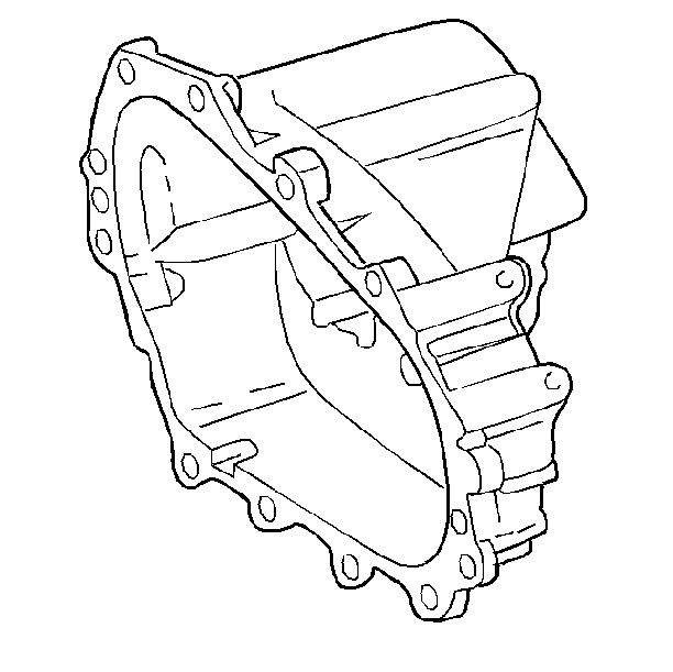
- Apply an 1/8 inch
bead of RTV sealer (GM P/N 12345739) or the equivalent to the rear case sealing
surfaces.
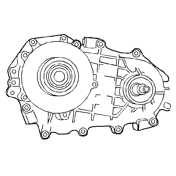
- Install the front cover.
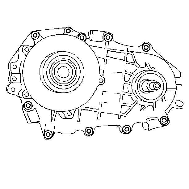
- Install the front cover
bolts.
Tighten
Tighten the bolts to 42 N·m (30 lb ft).
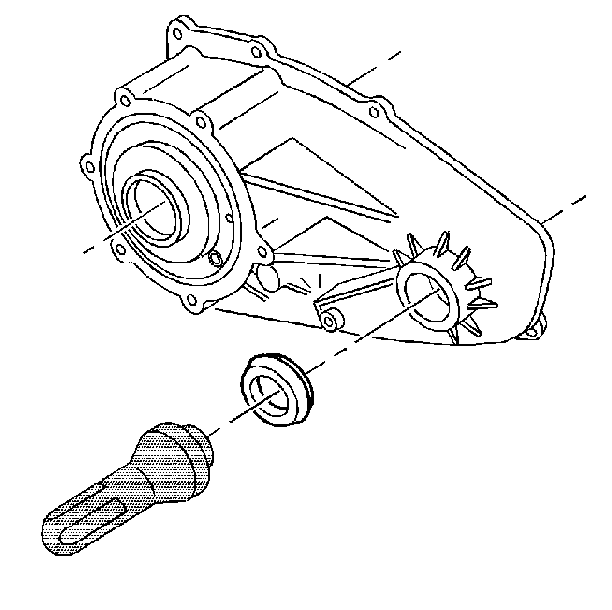
- Use the J 37668
in order to install the front output
shaft oil seal.
Lubricate the sealing lips with automatic transmission fluid.
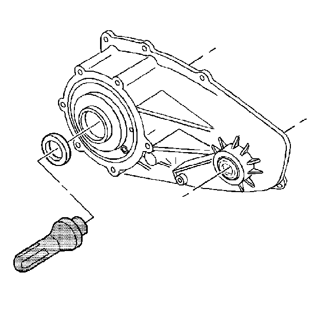
- Use the J 38216
in order to install the input shaft
oil seal.
Lubricate the sealing lips with automatic transmission fluid.
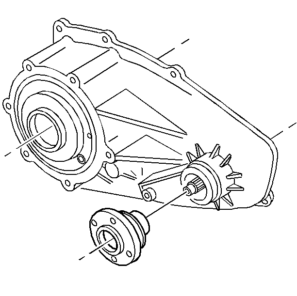
- Install the front output
flange.
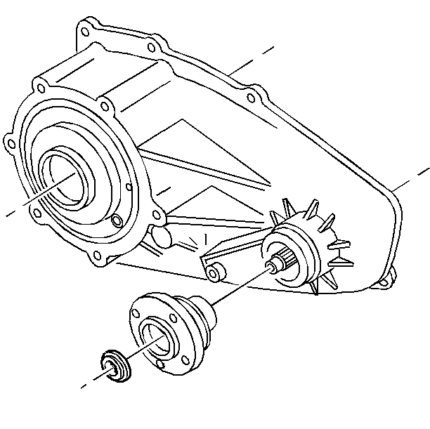
- Install the rubber sealing
washer.
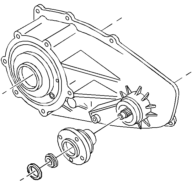
- Install the washer.
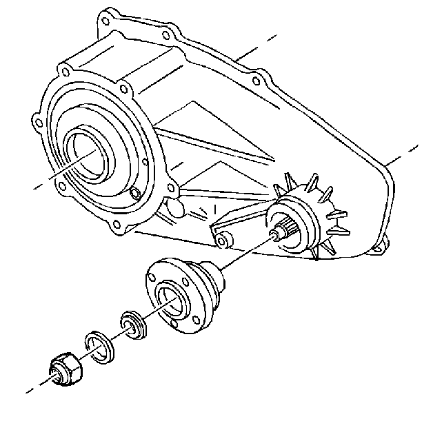
- Install the nut.
Tighten
Tighten the nut to 108 N·m (80 lb ft).


