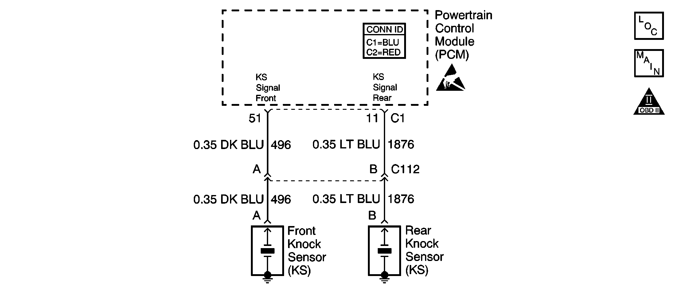
Circuit Description
The knock sensor (KS) system monitors both knock sensors in order to determine if detonation is present. If the KS system determines that excessive knock is present, the powertrain control module (PCM) retards the spark timing based on the signals from the KS system. When knock is present, the KS system voltage input signal to the PCM goes low. The PCM then retards timing until no knock is present. When the KS system is malfunctioning, the KS circuit voltage going to the PCM goes low. The PCM interprets this low signal as spark knock.
Conditions for Running the DTC
| • | The engine speed is between 1,500 RPM and 3,000 RPM. |
| • | The MAP is less than 44 kPa. |
| • | The engine coolant temperature (ECT) is more than 60°C (140°F). |
| • | The throttle angle is more than 0.5 percent. |
| • | The engine run time is more than 20 seconds. |
Conditions for Setting the DTC
| • | A malfunction with the KS system or circuits within the PCM are faulty. |
| • | All of the above conditions are present for 3 seconds. |
Action Taken When the DTC Sets
| • | The PCM illuminates the malfunction indicator lamp (MIL) on the second consecutive ignition cycle that the diagnostic runs and fails. |
| • | The PCM records the operating conditions at the time the diagnostic fails. The first time the diagnostic fails, the PCM stores this information in the Failure Records. If the diagnostic reports a failure on the second consecutive ignition cycle, the PCM records the operating conditions at the time of the failure. The PCM writes the conditions to the Freeze Frame and updates the Failure Records. |
Conditions for Clearing the MIL/DTC
| • | The PCM turns OFF the malfunction indicator lamp (MIL) after 3 consecutive ignition cycles that the diagnostic runs and does not fail. |
| • | A last test failed, or current DTC, clears when the diagnostic runs and does not fail. |
| • | A history DTC clears after 40 consecutive warm-up cycles, if no failures are reported by this or any other emission related diagnostic. |
| • | Use a scan tool in order to clear the MIL and the DTC. |
Diagnostic Aids
Important: Remove any debris from the PCM connector surfaces before servicing the PCM. Inspect the PCM connector gaskets when diagnosing or replacing the PCM. Ensure that the gaskets are installed correctly. The gaskets prevent water intrusion into the PCM.
| • | If the diagnostic test does not run, review the Conditions for Running the DTC. |
| • | For an intermittent condition, refer to Symptoms . |
Test Description
The number below refers to the step number on the diagnostic table.
Step | Action | Value(s) | Yes | No |
|---|---|---|---|---|
1 | Did you perform the Powertrain On-Board Diagnostic (OBD) System Check? | -- | ||
|
Important:: The replacement PCM must be programmed. Replace the PCM. Refer to Powertrain Control Module Replacement . Is the action complete? | -- | -- | ||
3 |
Does the scan tool indicate that this test ran and passed? | -- | ||
4 | Select the Capture Info option and the Review Info option using the scan tool. Does the scan tool display any DTCs that you have not diagnosed? | -- | Go to the applicable DTC table | System OK |
