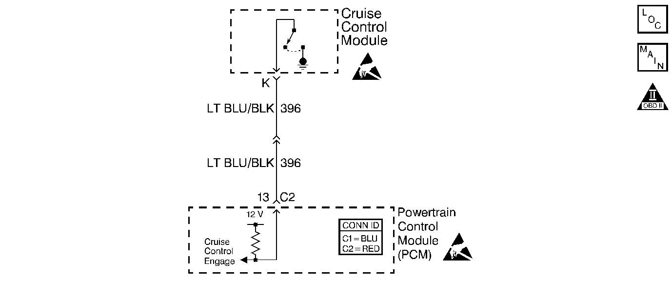
Circuit Description
The cruise control module signals the powertrain control module (PCM) when the cruise system is active. The PCM supplies a B+ voltage to the cruise control engage circuit. The cruise control module grounds the signal circuit to the PCM when the cruise is enabled. The PCM then modifies transmission shift patterns based on the cruise conditions. The PCM also sends a Class 2 message to the instrument panel cluster (IPC) to illuminate the cruise indicator.
Diagnostic Aids
Important: Remove any debris from the PCM connector surfaces before servicing the PCM. Inspect the PCM connector gaskets when diagnosing and replacing the PCM. Ensure that the gaskets are installed correctly. The gaskets prevent water intrusion into the PCM.
| • | The following may cause an intermittent: |
| - | Mis-routed harness |
| - | Rubbed through wire insulation |
| - | Broken wire inside the insulation |
| • | For an intermittent, refer to Symptoms . |
Test Description
The numbers below refer to the step numbers on the diagnostic table
-
This step is inspecting for a short to ground.
-
This step is inspecting the cruise engage circuit for a short to another PCM circuit.
-
If no continuity is displayed on the DMM, inspect for a poor connection at the C100 16 way black connector. Refer to Testing for Intermittent Conditions and Poor Connections in Wiring Systems.
Step | Action | Value(s) | Yes | No |
|---|---|---|---|---|
1 |
Important: If there are any Class 2 diagnostic trouble codes (DTCs) set, refer to applicable DTC before proceeding with this diagnostic. Did you perform the Powertrain On-Board Diagnostic (OBD) System Check? | -- | ||
2 | Is the customer concern that the cruise control is inoperative? | -- | Go to Cruise Control Inoperative in Cruise Control | |
3 |
Does the scan tool display the instrument panel cluster (IPC) as Active? | -- | Go to Diagnostic System Check - Instrument Cluster in Instrument Panel, Gauges and Console | |
4 |
Does the scan tool display Cruise Engaged as YES? | -- | ||
Does the DMM display the specified value? | B+ | |||
6 | Ground the cruise control engage circuit using a fused jumper wire. Refer to Using Fused Jumper Wires in Wiring Systems. Does the scan tool display Cruise Engaged as YES? | -- | ||
7 |
Does the scan tool display cruise engaged as YES? | -- | Go to CRUISE Indicator Always On in Cruise Control | |
8 |
Is continuity displayed on the DMM? | -- | ||
Inspect the continuity of the cruise control engage circuit to all other PCM circuits in the harness connector using the DMM. Refer to Testing for Continuity in Wiring Systems. Is continuity displayed on the DMM? | -- | |||
10 |
Is continuity displayed on the DMM? | -- | ||
11 |
Important: Monitor the cruise indicator lamp for each step
Does the cruise indicator lamp turn ON when the circuit is grounded and OFF when the circuit is opened. | -- | Go to CRUISE Indicator Always On in Cruise Control | |
12 |
Did you find and correct the condition? | -- | System OK | Go to CRUISE Indicator Always On in Cruise Control |
13 | Repair the grounded cruise control engage circuit between the PCM and the cruise control module. Refer to Wiring Repairs in Wiring Systems. Is the action complete? | -- | System OK | -- |
14 | Repair the short between the cruise control engage circuit and the circuit that displayed continuity. Is the action complete? | -- | System OK | -- |
Repair the open cruise control engage circuit between the PCM and the cruise control module. Refer to Wiring Repairs in Wiring Systems. Is the action complete? | -- | System OK | -- | |
16 |
Did you find and correct the condition? | -- | System OK | |
17 |
Important:: Program the replacement PCM. Replace the PCM. Refer to Powertrain Control Module Replacement . Is the replacement complete? | -- | System OK | -- |
