Disassembly Procedure
Tools Required
J 8059 Snap Ring
Pliers
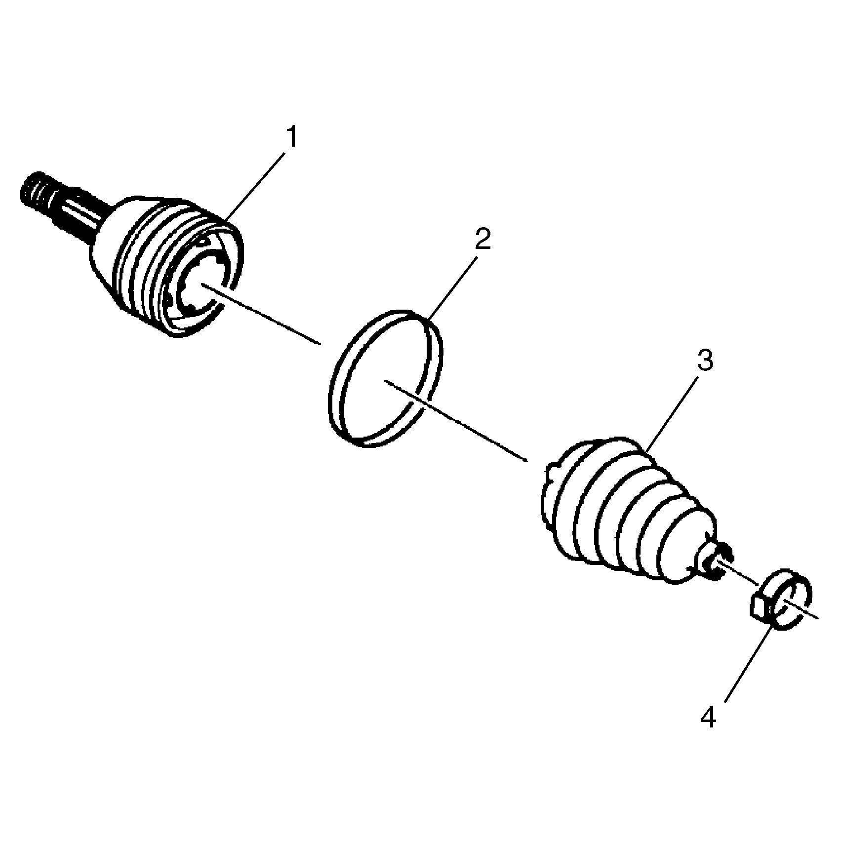
- Place protective covers
over the vise jaws. Place the halfshaft in the vise.
- Use a hand grinder to cut through the swage ring (2).
- Use side cutters to cut off the small boot clamp (4).
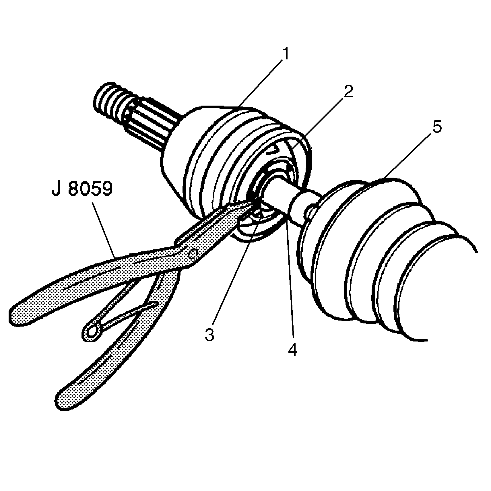
- Slide the boot (5)
down the halfshaft bar (4) and away from the CV joint outer race (1).
- Wipe all grease away from the face of the CV joint.
- Find the halfshaft bar retaining snap ring (3), which is
located in the inner race (2).
- Spread the snap ring ears apart using J 8059
(or equivalent).
- Pull the CV joint (1) and the CV joint boot (5)
from the halfshaft bar (4).
- Discard the old CV joint boot (5).
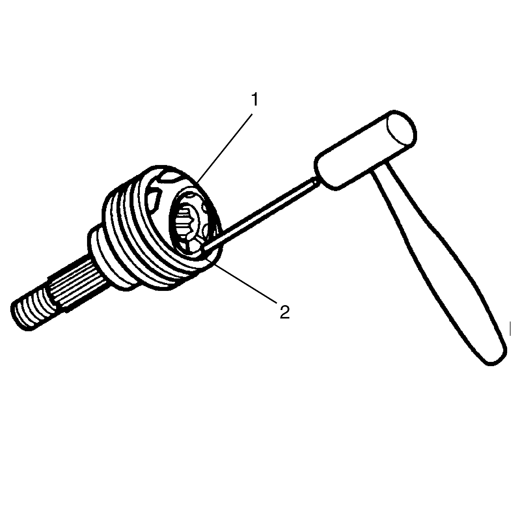
- Place a brass drift against
the CV joint cage (1).
- Tap gently on the brass drift with a hammer in order to tilt the
cage (1).
- Remove the first chrome alloy ball (2) when the CV joint
cage (1) tilts.
- Tilt the CV joint cage (1) in the opposite direction to
remove the opposing chrome alloy ball (2).
- Repeat this process to remove all six of the balls.
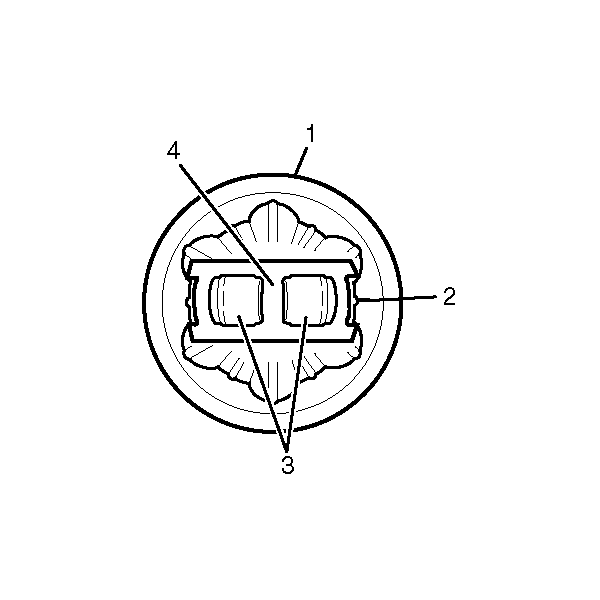
- Pivot the CV joint cage (4)
and the inner race 90 degrees to the center line of the outer race (1).
At the same time, align the cage windows (3) with the lands of the
outer race (2).
- Lift out the cage (4) and the inner race.
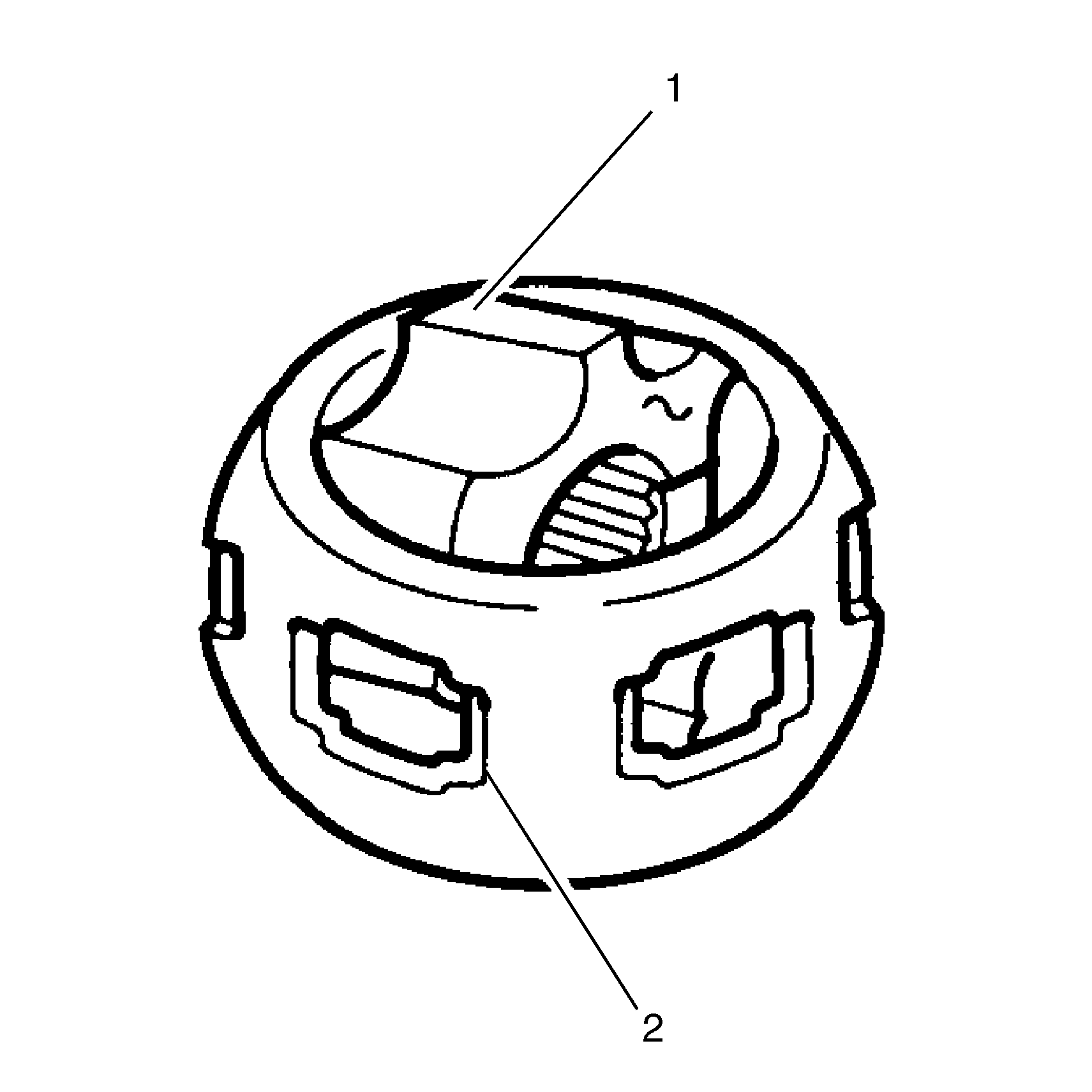
- Remove the inner race (1)
from the cage (2) by rotating the inner race (1) upward.
- Clean the following items thoroughly with cleaning solvent. Remove
all traces of old grease and any contaminates.
| 18.1. | The inner and outer race assemblies |
| 18.3. | The chrome alloy balls |
- Dry all the parts.
- Check the CV joint assembly for unusual wear, cracks, or other
damage.
- Replace any damaged parts.
- Clean the halfshaft bar. Use a wire brush to remove any rust in
the boot mounting area (grooves).
Assembly Procedure
Tools Required
| • | J 36652 -98
Split Plate Swage Clamp (K15 models) |
| • | J 36652 -1
Split Plate Swage Clamp (K25 models) |
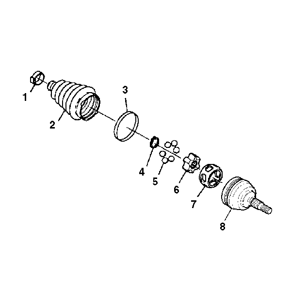
- Inspect all of the parts
for unusual wear, cracks, or other damage. Replace the CV joint assembly
if necessary.
- Put a light coat of the recommended grease on the inner (6)
and the outer race (8) grooves.

- Hold the inner race (1)
at 90 degrees to the centerline of the cage (2).
- Align the lands of the inner race (1) with the windows
of the cage (2).
- Insert the inner race (1) into the cage (2), by
rotating the inner race (1) downward.

- Insert the cage (4)
and inner race into the outer race (1).

- Place a brass drift against
the CV joint cage (1).
- Tap gently on the brass drift with a hammer in order to tilt the
cage (1).
- Install the first chrome alloy ball (2) when the CV joint
cage (1) tilts.
- Tilt the CV joint cage (1) in the opposite direction to
install the opposing chrome alloy ball (2).
- Repeat this process in order to install all six of the balls.
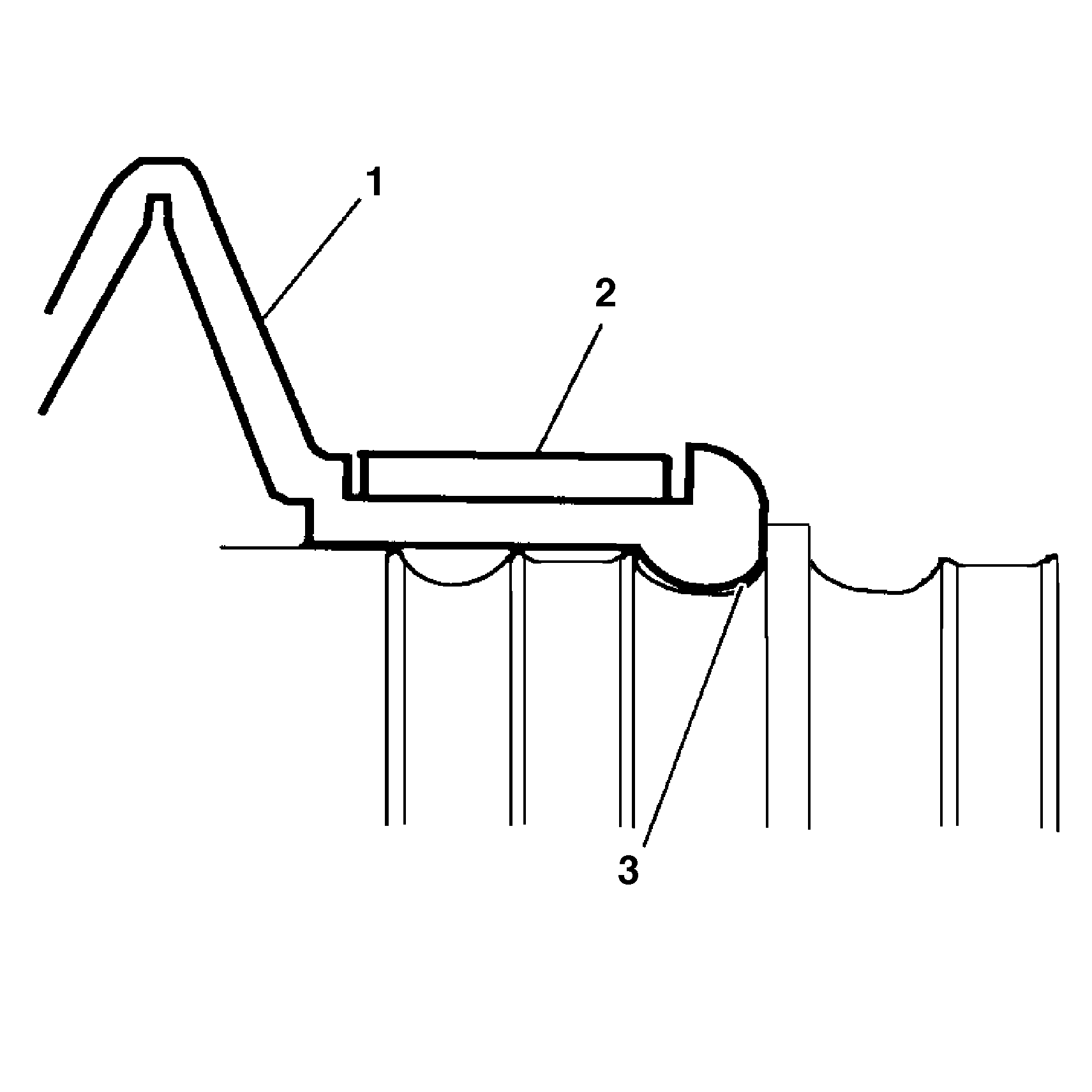
- Pack the CV joint boot (1)
and the CV joint assembly with the grease supplied in the kit. The amount
of grease supplied in this kit has been pre-measured for this application.
- Place the new small boot clamp (2) onto the CV joint boot (1).
- Slide the CV joint boot (1) onto the halfshaft bar.
- Position the small end of the CV joint boot (1) into the
joint boot groove (3) on the halfshaft bar.
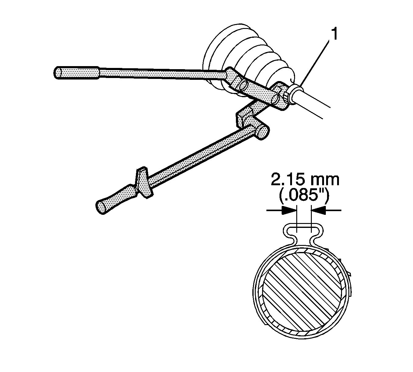
- Secure the small boot
clamp (1) using J 35910
(or equivalent), a breaker bar, and a torque wrench.
Tighten
Tighten the small clamp (1) to 136 N·m (100 lb ft).
- Check the gap dimension on the clamp ear. Continue tightening
until the gap dimension is reached.
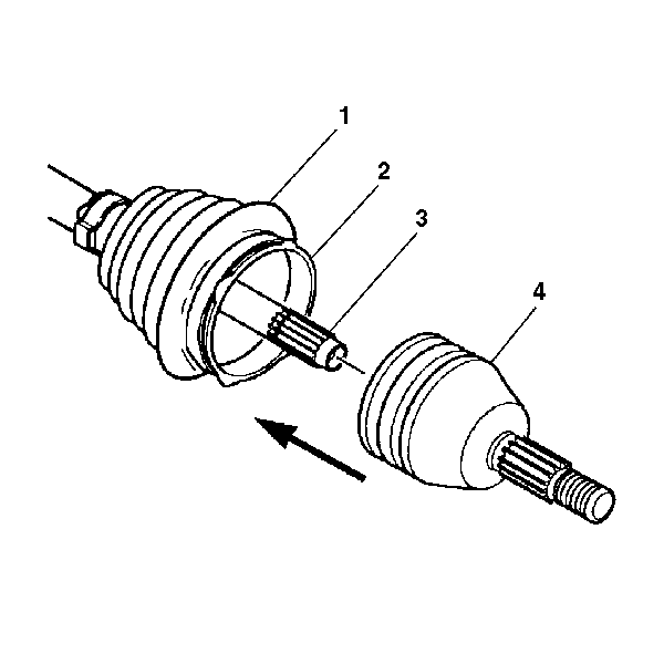
- Pinch the new swage ring (2)
slightly by hand to distort it into an oval shape.
- Slide the distorted swage ring (2) over the large diameter
of the boot (1).
Important: Be sure that the retaining ring side of the CV joint inner race faces
the halfshaft bar (3) before installation.
Slide the CV joint (4) onto the halfshaft bar (3). The
retaining snap ring inside of the inner race engages in the halfshaft bar
groove with a click when the CV joint (4) is in the proper position.
- Pull on the CV joint (4) to verify engagement.
- Slide the large diameter of the CV joint boot (1), with
the large swage ring (2) in place, over the outside edge of the CV
joint outer race (4).
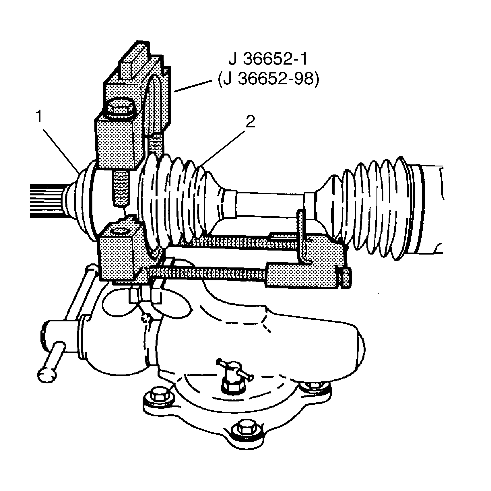
- Clamp the CV joint boot (2)
tightly to the CV joint outer race (1) with the large swage ring (4),
using the following procedure:
| 22.2. | Install the bottom half of the split-plate swage clamp. For K15
models, use J 36652
-98. |
| 22.3. | For K25 models, use J 36652
-1. |
| 22.4. | Position the CV joint end (outboard end) of the halfshaft assembly
in the bottom half of J 36652
. |
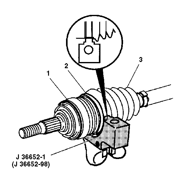
- Align the following during
this procedure:
| • | The CV joint assembly (1) |
- Install the top half of J 36652
onto the lower half of the tool, over the CV joint boot (3)
and the CV joint assembly (1).
- Align the swage ring (2) and the swage ring clamp.
- Insert the bolts into J 36652
. Hand tighten the bolts until the bolts are snug.
Tighten
Tighten each bolt 180 degrees at a time. Alternate between the
bolts until both sides of the top half of J 36652
touch the bottom half of the tool.
- Loosen the bolts and remove the halfshaft assembly from J 36652
.


