For 1990-2009 cars only
Control Assembly Replacement Heat only
Removal Procedure
- Remove the instrument panel (IP) bezel. Refer to Instrument Panel Cluster Trim Plate Bezel Replacement in Instrument Panel, Gauges and Console.
- Remove the radio. Refer to Radio Replacement in Entertainment.
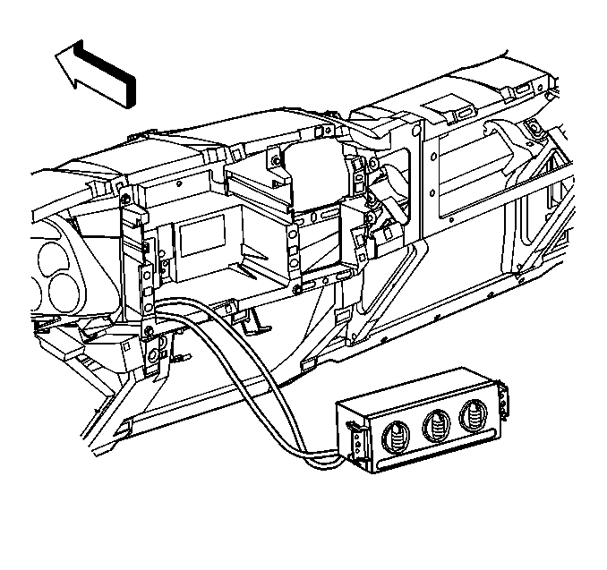
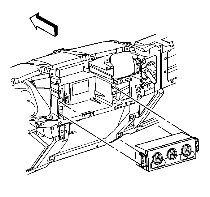
- Remove the heater control assembly by firmly depressing and holding the retaining tabs. Slide the assembly forward.
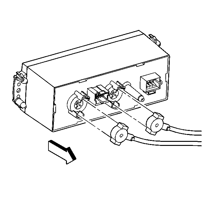
- Disconnect the temperature and the mode cables from the back of the control assembly.
- Disconnect the electrical connection from the control assembly.
- Remove the control assembly.


Installation Procedure
- Connect the electrical connection to the control assembly.
- Connect the temperature and the mode cables to the back of the control assembly.
- Install the control assembly to the IP carrier until you hear an audible snap.
- Install the radio. Refer to Radio Replacement in Entertainment.
- Install the IP bezel. Refer to Instrument Panel Cluster Trim Plate Bezel Replacement in Instrument Panel, Gauges and Console.


Control Assembly Replacement Heat and A/C
Removal Procedure
- Remove the instrument cluster trim plate bezel. Refer to Instrument Panel Cluster Trim Plate Bezel Replacement in Instrument Panel, Gauges, and Console.
- Remove the IP storage tray.
- Remove the inflatable restraint module switch form the instrument panel. Refer to Inflatable Restraint Instrument Panel Module Disable Switch Replacement in Restraints.
- Remove the control assembly.
- Disconnect the electrical connectors from the control assembly.

| 4.1. | Release the retaining tabs. |
| 4.2. | Pull the control head out of the instrument panel carrier. |
Installation Procedure
- Connect the electrical connectors to the control assembly.
- Install the control assembly.
- Install the inflatable restraint module switch to the instrument panel. Refer to Inflatable Restraint Instrument Panel Module Disable Switch Replacement in Restraints.
- Install the IP storage tray.
- Install the instrument cluster trim plate bezel. Refer to Instrument Panel Cluster Trim Plate Bezel Replacement in Instrument Panel, Gauges, and Console.

