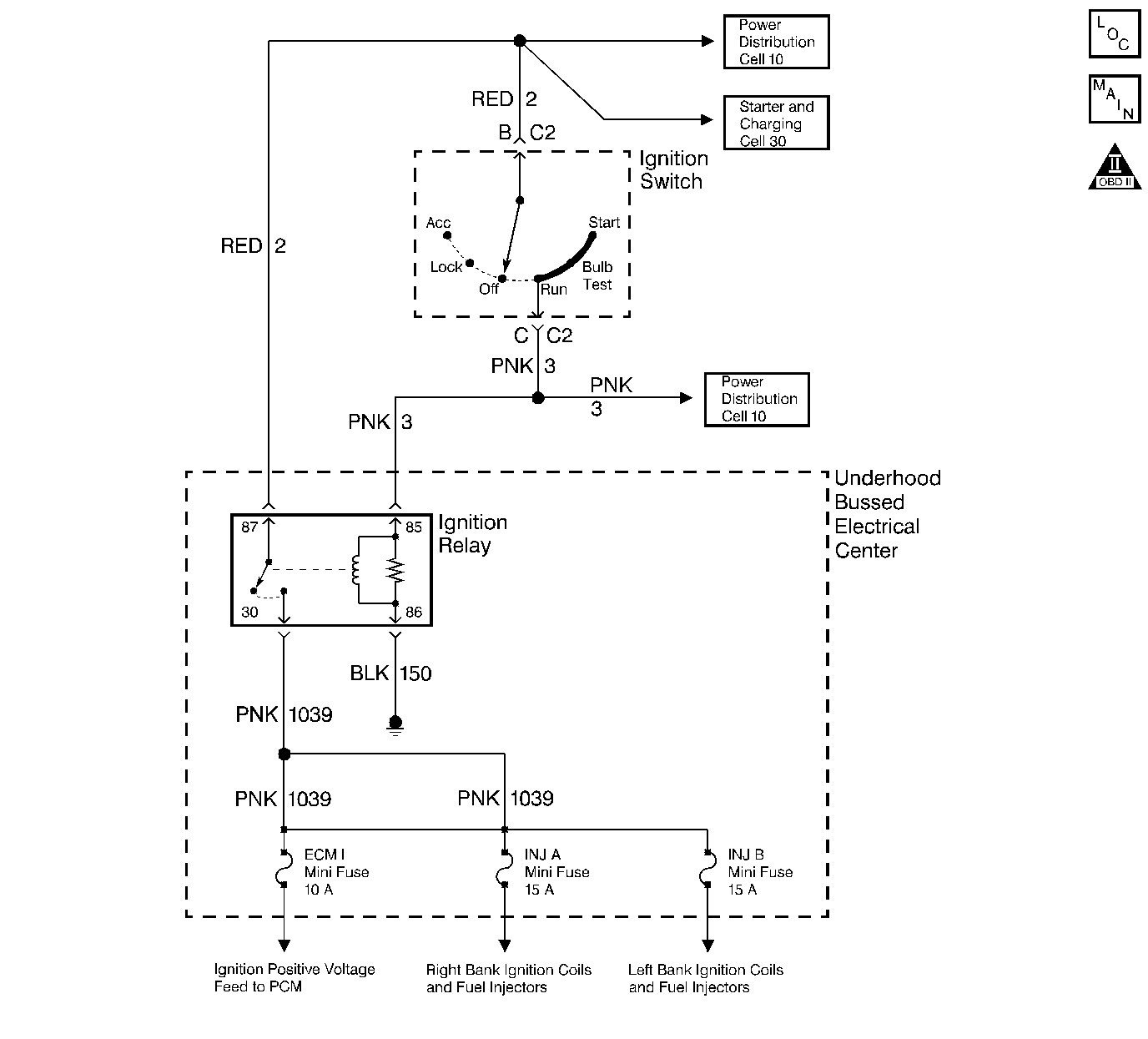
Circuit Description
The ignition relay supplies ignition voltage to the following components:
| • | Injectors and ignition coils |
| • | AIR relay |
Diagnostic Aids
The following may cause an intermittent:
| • | Poor connections -- Check for adequate terminal tension. Refer to Testing for Intermittent Conditions and Poor Connections in Wiring Systems. |
| • | Corrosion |
| • | Mis-routed harness |
| • | Rubbed through wire insulation |
| • | Broken wire inside the insulation |
Test Description
The numbers below refer to the step numbers on the diagnostic table.
-
Refer to Thumbnail Schematic for proper relay terminal identification.
-
This step is testing the relay ground circuit.
-
This step isolates the circuit from the IGN relay. All of the circuits at the relay are good if the test lamp illuminates.
-
The open circuit will be between the splice and the IGN relay.
-
Remove the underhood electrical center cover and inspect the circuits that are supplied a voltage by the IGN relay.
Step | Action | Value(s) | Yes | No | ||||||
|---|---|---|---|---|---|---|---|---|---|---|
1 | Did you perform the Powertrain On-Board Diagnostic (OBD) System Check? | -- | ||||||||
Does the test lamp illuminate? | -- | |||||||||
3 |
Does the test lamp illuminate? | -- | ||||||||
Is the resistance less than the specified value? | 0-5 ohms | |||||||||
Does the test lamp illuminate? | -- | |||||||||
6 | Inspect for poor terminal contact at the IGN relay underhood electrical center connector. Refer to Testing for Intermittent Conditions and Poor Connections in Wiring Systems. Did you find and correct the condition? | -- | System OK | |||||||
7 | Replace the IGN relay. Is the action complete? | -- | System OK | -- | ||||||
8 | Repair the open or short to ground in the battery positive voltage supply to the IGN relay. Refer to Wiring Repairs in Wiring Systems. Is the action complete? | -- | System OK | -- | ||||||
Repair the ignition positve voltage circuit to the IGN relay. Refer to Wiring Repairs in Wiring Systems. Is the action complete? | -- | System OK | -- | |||||||
Replace the underhood electrical center. Refer to Underhood Fuse Block Replacement in Engine Electrical. Is the action complete? | -- | System OK | -- |
