For 1990-2009 cars only
Removal Procedure
- Position the steering column shift lever to the park position.
- Remove the instrument panel knee bolster. Refer to Knee Bolster Replacement in Instrument Panel, Gages, and Console.
- Remove the driver's seat. Refer to Front Seat Replacement - Bucket in Seats.
- Pull back the carpet and insulation around the driver's area.
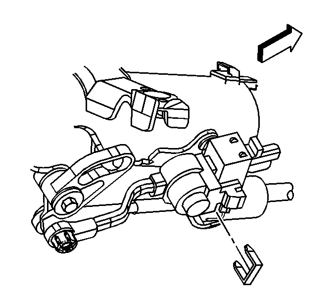
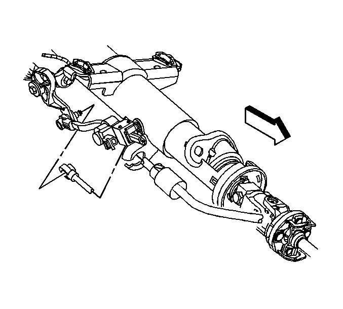
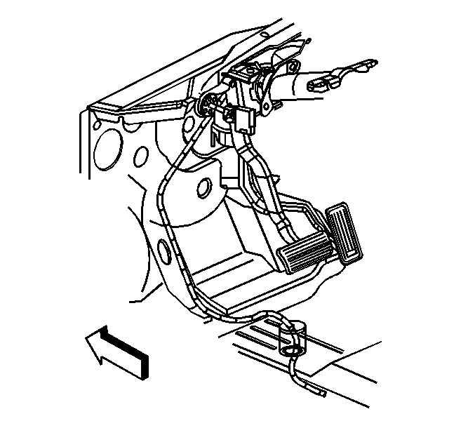
- Remove the retainer securing the cable to the steering column.
- Remove the cable end from the steering column ball stud.
- Depress the tangs and remove the cable from the steering column bracket.
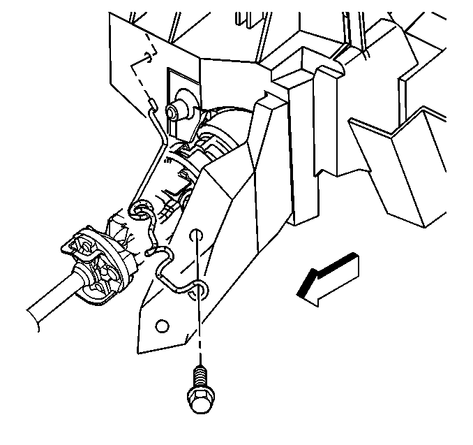
- Remove the bolt securing the cable support to the brace.
- Remove the range selector cable from the support.
- Remove the cable grommet from the floor panel.
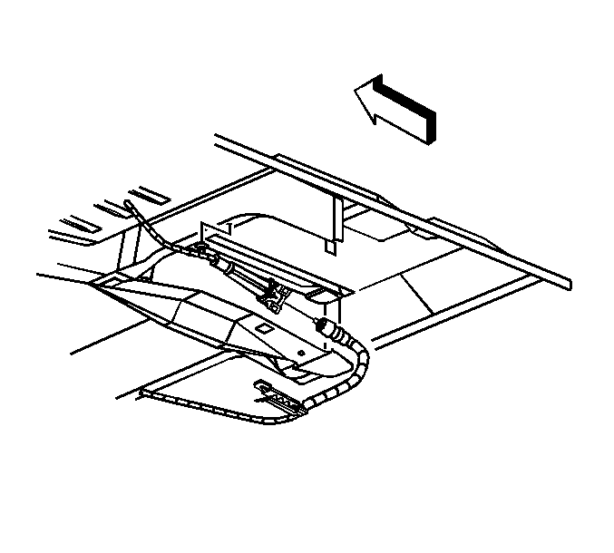
- Raise and suitably support the vehicle. Refer to in General Information.
- Remove the clips on the cable from the floor panel reinforcement.
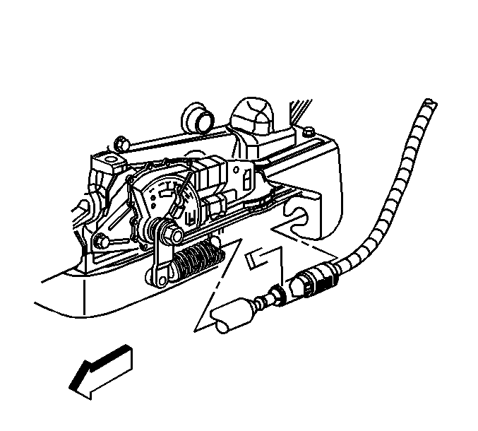
- Ensure the transmission manual shaft is positioned in mechanical park.
- Remove the retainer that secures the cable to the bracket.
- Remove the cable clip on the transfer case, if equipped.
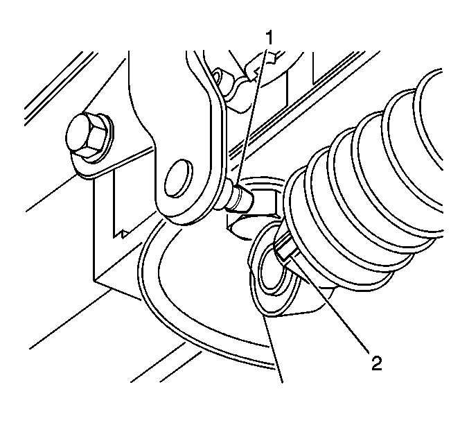
- Remove the range selector cable end (2) from the transmission range selector lever ball stud (1).
- Depress the tangs and remove the cable from the bracket.
- Lower the vehicle and ensure that the steering column shift lever is still in the park position.
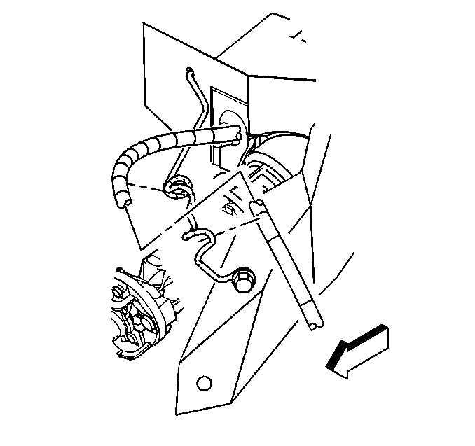
Important: Avoid unnecessary twisting/bending of the range selector cable when removing the cable from the support.
Installation Procedure
- Ensure that the transmission manual shaft lever is in the mechanical park position.
- Align and install the cable to the bracket.
- Install the range selector cable end (2) to the transmission range selector lever ball stud (1).
- Install the cable clip on the transfer case, if equipped.
- Install the retainer that secures the cable to the bracket.
- Install the clips on the cable to the floor panel reinforcement.
- Lower the vehicle.
- Install the cable grommet to the floor panel.
- Install the range selector cable to the support.
- Install the bolt securing the cable support to the brace.
- Install the cable to the steering column bracket.
- Ensure the tangs fully seat (snap) into the steering column bracket.
- Install the cable end to the steering column ball stud.
- Install the retainer securing the cable to the steering column.
- Position the carpet and insulation around the driver's area.
- Install the driver's seat. Refer to Front Seat Replacement - Bucket in Seats.
- Install the instrument panel knee bolster. Refer to Knee Bolster Replacement in Instrument Panel, Gages, and Console.
- Test the transmission for proper shift operation.
- If all of the gear positions cannot be achieved, the shift cable must be re-adjusted. Refer to cable adjustment below.


Important: Avoid unnecessary twisting/bending of the range selector cable when installing the cable to the support.
Notice: Refer to Fastener Notice in the Preface section.

Tighten
Tighten the bolt to 10 N·m (89 lb in).


Cable Adjustment
- Ensure that the steering column shift lever is in the park (P) position.
- Raise and suitably support the vehicle. Refer to Lifting and Jacking the Vehicle in General Information.
- Ensure that the transmission manual shaft lever is in the park (P) position.
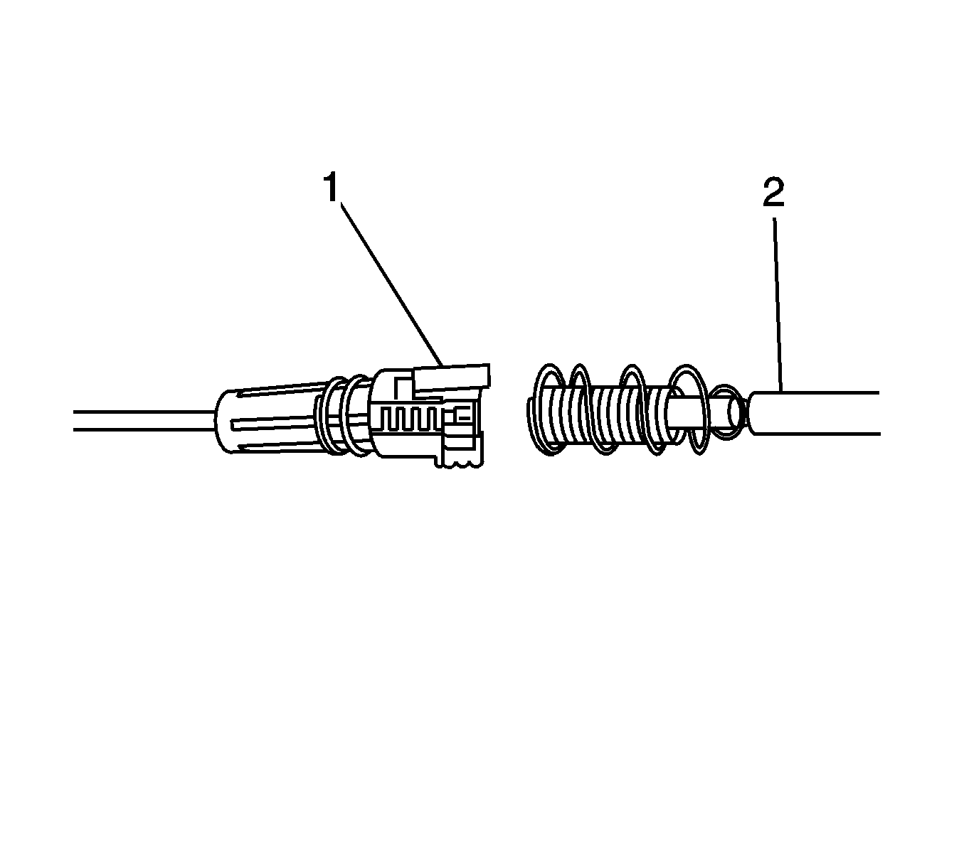
- Grasp the shift cable shifter end (1) in the left hand and the shift cable transmission end (2) in the right hand.
- Align the outside diameter of the transmission end (2) with the inside diameter of the shifter end (1).
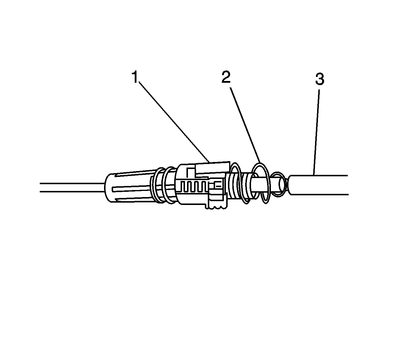
- Push the end of the transmission cable (3) inside the shifter end until the blue spring (2) on the transmission end (3) is fully compressed, this will engage the inner wire and lock both wires together.
- Release the transmission end (3) and allow the spring (2) to tension/adjust the cable system.
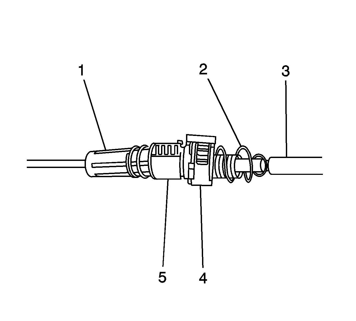
- Pull the white cover (5) on the shifter end (1) back.
- Push the natural colored lock button (4) down to engage the locking teeth on the transmission end (3).
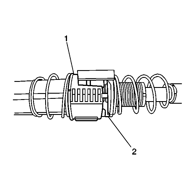
- Release the white cover (1).
- Verify the white cover (1) conceals the natural colored lock (2).
- If the white cover (1) does not conceal the natural colored lock (2), the shift cable must be re-adjusted. Refer to cable re-adjustment below.
- Lower the vehicle.
- Test the transmission for proper shift operation.
- If all of the gear positions cannot be achieved, the shift cable must be re-adjusted. Refer to cable re-adjustment below.
Important: DO NOT hold the transmission end (1) during this operation, this will result in a mis-adjusted cable.
Cable Re-Adjustment
- Place the steering column shift lever back into the park (P) position.
- Raise the vehicle.
- Ensure that the transmission manual shaft lever is in the park (P) position.
- Pull the white cover (1) back to expose the natural colored lock (2). Under the lock (2), insert a flat bladed screwdriver under the lock ramp located at the top of the lock. The lock will pop up, and the transmission end will move slightly away from the shifter end.
- Push the end of the transmission end (3) inside the shifter end (1) until the blue spring (2) on the transmission end (3) is fully compressed, this will engage the inner wire and lock both wires together.
- Release the transmission end (3) and allow the spring (2) to tension/adjust the cable system.
- Pull the white cover (5) on the shifter end (1) back.
- Push the natural colored lock button (4) down to engage the locking teeth on the transmission end (3).
- Release the white cover (1).
- Verify the white cover (1) conceals the natural colored lock (2).


Important: DO NOT hold the transmission end (1) during this operation, this will result in a mis-adjusted cable.

