Tools Required
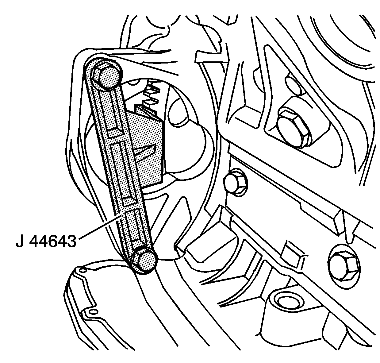
J 44643 Flywheel Holding Tool
Removal Procedure
- Disconnect the battery negative cables. Refer to Battery Negative Cable Disconnection and Connection in Engine Electrical.
- Raise and support the vehicle. Refer to Lifting and Jacking the Vehicle in General Information.
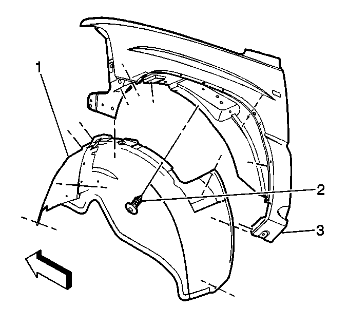
- Remove the right front fender wheelhouse panel (1).
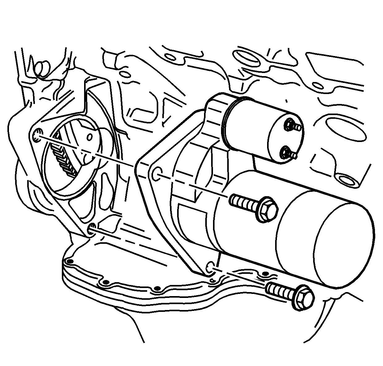
- Remove the starter motor and set aside. The wiring to the starter does not require removal.
- Install the J 44643 in the starter motor opening in order to hold the engine from turning.
- Lower the vehicle.
- Remove the upper and lower fan shroud. Refer to Engine Coolant Fan Upper Shroud Replacement and Engine Coolant Fan Lower Shroud Replacement in Engine Cooling.
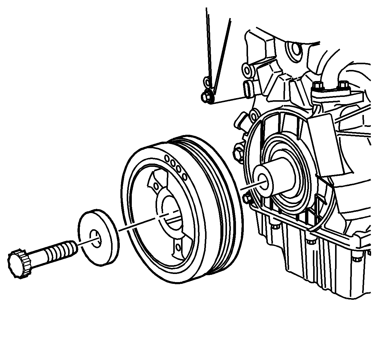
- Remove a crankshaft balancer bolt.
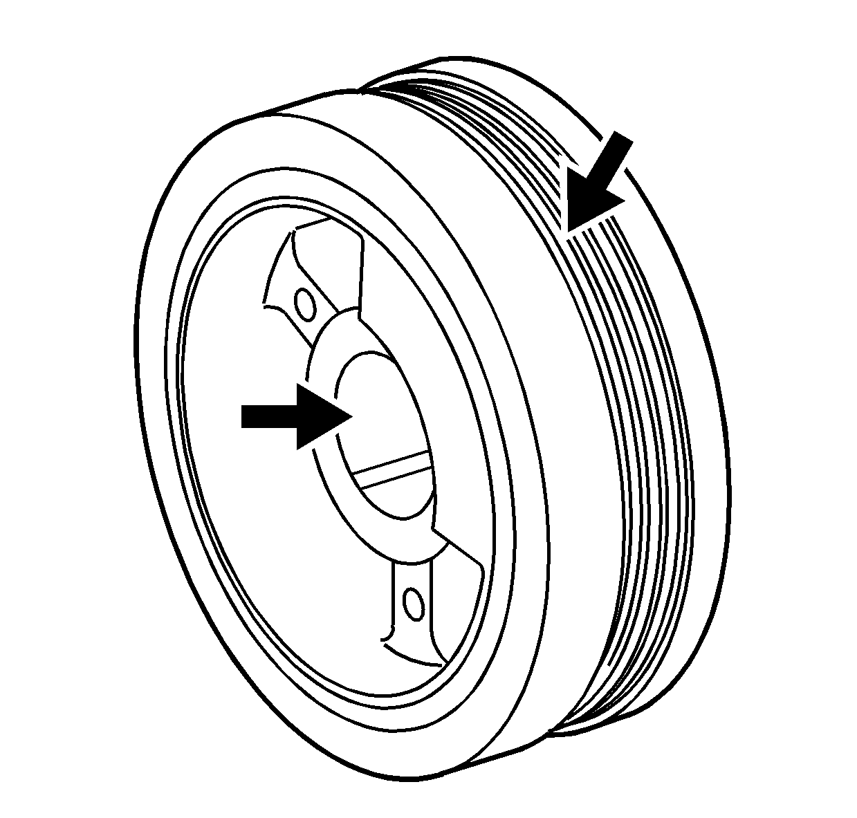
- Remove the crankshaft balancer.
- Inspect the pin in the crankshaft for wear.
- Replace the pin in the crankshaft if worn.
- Clean the crankshaft balancer in suitable cleaning solvent and air dry.
- Inspect for cracking, belt drive surface damage, or other damage to the crankshaft balancer.
- Inspect the crankshaft balancer keyway for crankshaft pin wear.
- Replace the crankshaft balancer if damage is found.
The balancer is a slip fit and should slide off.
During removal if the balancer could be turned side to side the pin is worn.
Installation Procedure
- Lightly lubricate the crankshaft balancer internal hub with engine oil.
- Install the crankshaft balancer on the crankshaft.
- Lightly lubricate the crankshaft balancer bolt with engine oil.
- Install the crankshaft balancer bolt.
- Raise the vehicle.
- Remove the J 44643 .
- Install the starter motor and bolts.
- Install the right front fender wheelhouse panel (1).
- Lower the vehicle.
- Install the upper and lower fan shroud. Refer to Engine Coolant Fan Upper Shroud Replacement and Engine Coolant Fan Lower Shroud Replacement in Engine Cooling.
- Connect the battery negative cables. Refer to Battery Negative Cable Disconnection and Connection in Engine Electrical.

Notice: Use the correct fastener in the correct location. Replacement fasteners must be the correct part number for that application. Fasteners requiring replacement or fasteners requiring the use of thread locking compound or sealant are identified in the service procedure. Do not use paints, lubricants, or corrosion inhibitors on fasteners or fastener joint surfaces unless specified. These coatings affect fastener torque and joint clamping force and may damage the fastener. Use the correct tightening sequence and specifications when installing fasteners in order to avoid damage to parts and systems.
Tighten
Tighten the bolt with plain washer to 363 N·m (278 lb ft).

Tighten
Tighten the starter motor bolts to 78 N·m (58 lb ft).

