Special Tools
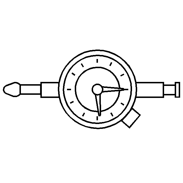
| • | J 45059 Torque Angle Meter |
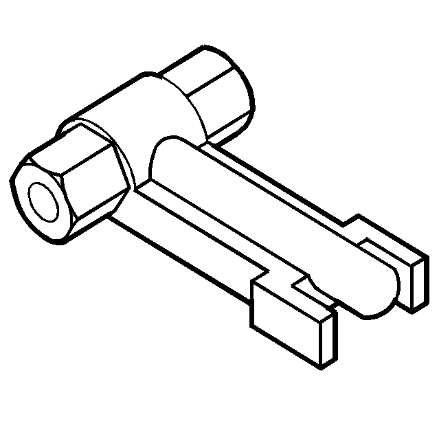
| • | J 44639 Injector Remover |
| • | J 26900-12 Dial Indicator |
| • | J 26900-13 Magnetic Base |
Removal Procedure
- Disconnect the battery negative cables. Refer to Battery Negative Cable Disconnection and Connection .
- Drain the engine coolant and the engine block. Refer to Cooling System Draining and Filling .
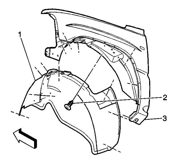
- Remove the right front fender wheelhouse inner panel (1).
- Remove the turbocharger. Refer to Turbocharger Replacement .
- Remove the turbocharger charged air cooler outlet duct.
- Remove the thermostat housing crossover. Refer to Thermostat Housing Crossover Replacement .
- Remove the right fuel rail assembly. Refer to Fuel Injection Fuel Rail Assembly Replacement - Bank 1 .
- Remove the right intake manifold. Refer to Intake Manifold Replacement - Right Side .
- Remove the upper right valve rocker arm cover. Refer to Valve Rocker Arm Cover Replacement - Upper Right Side .
- Remove the right exhaust manifold. Refer to Exhaust Manifold Replacement - Right Side .
- Remove the lower right valve rocker arm cover. Refer to Valve Rocker Arm Cover Replacement - Lower Left Side .
- Remove the valve rocker arm shaft assembly, pushrods, and valve bridges. Refer to Valve Rocker Arm, Shaft, and Push Rod Replacement .
- Remove the glow plugs. Refer to Glow Plug Replacement - Bank 1 .
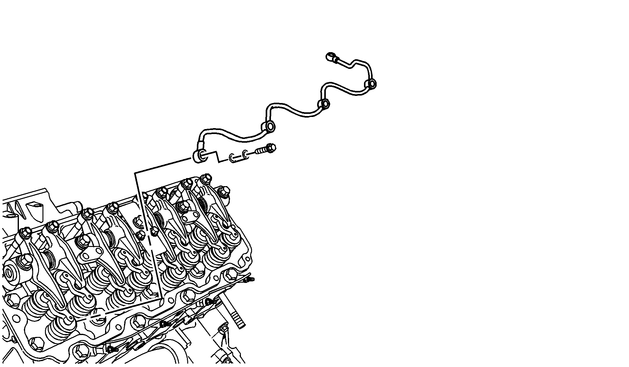
- Remove the fuel injector return pipe eye bolts and washers.
- Remove the fuel injector return pipe assembly.
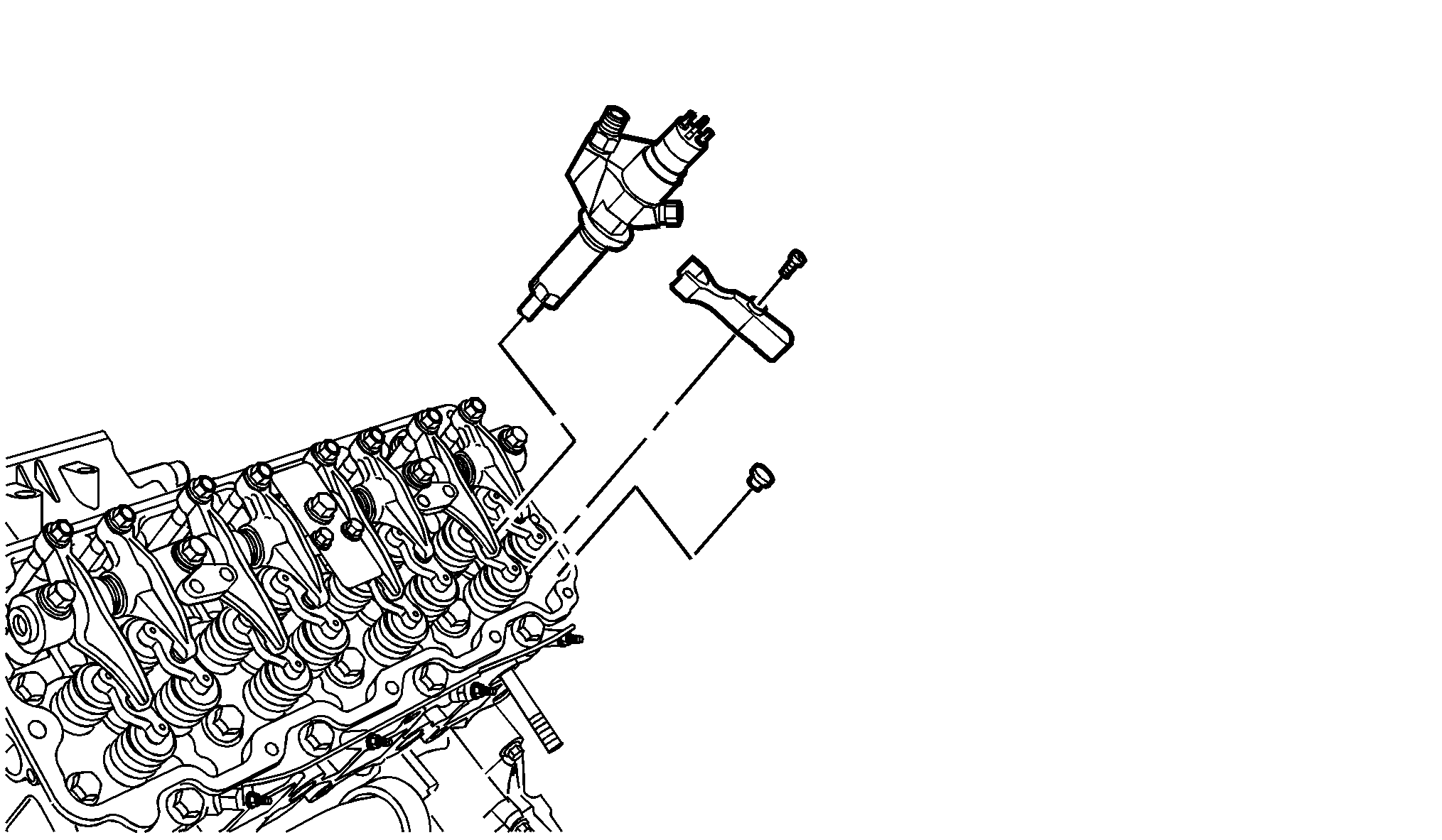
- Remove the fuel injector bracket bolts.
- Using the J 44639 , remove the fuel injectors with the fuel injector brackets.
- Remove the injector bracket pins.
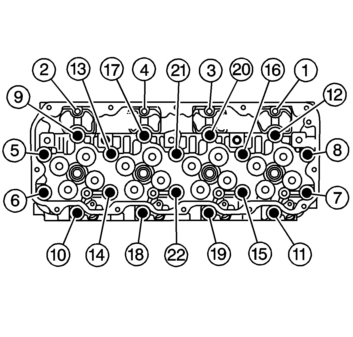
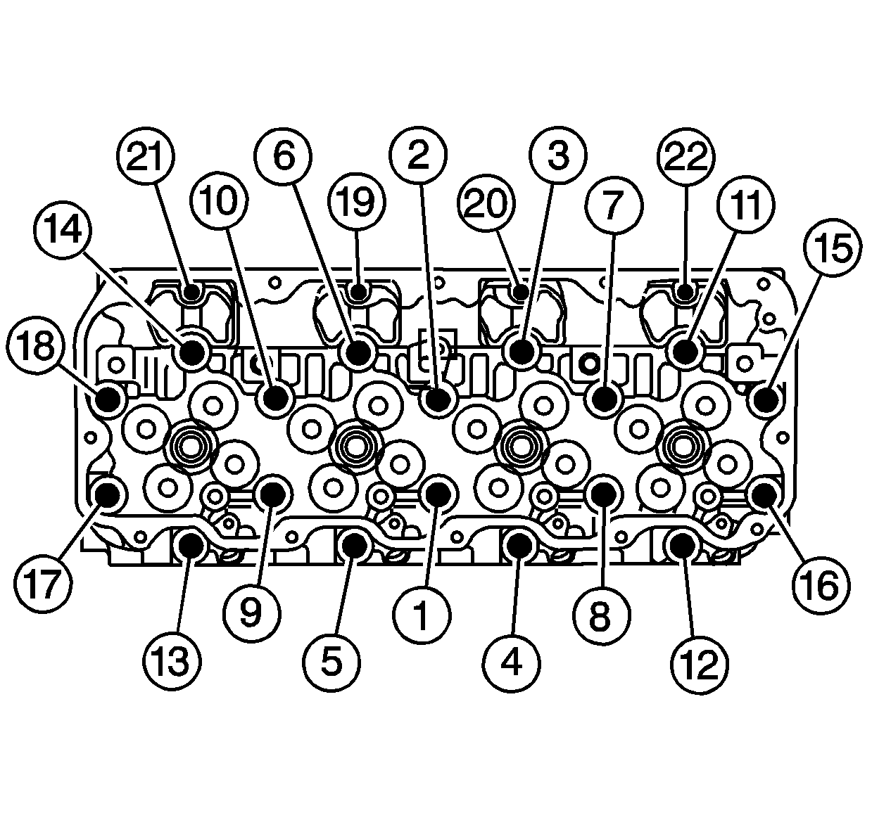
- Remove the cylinder head bolts in the proper sequence and discard.
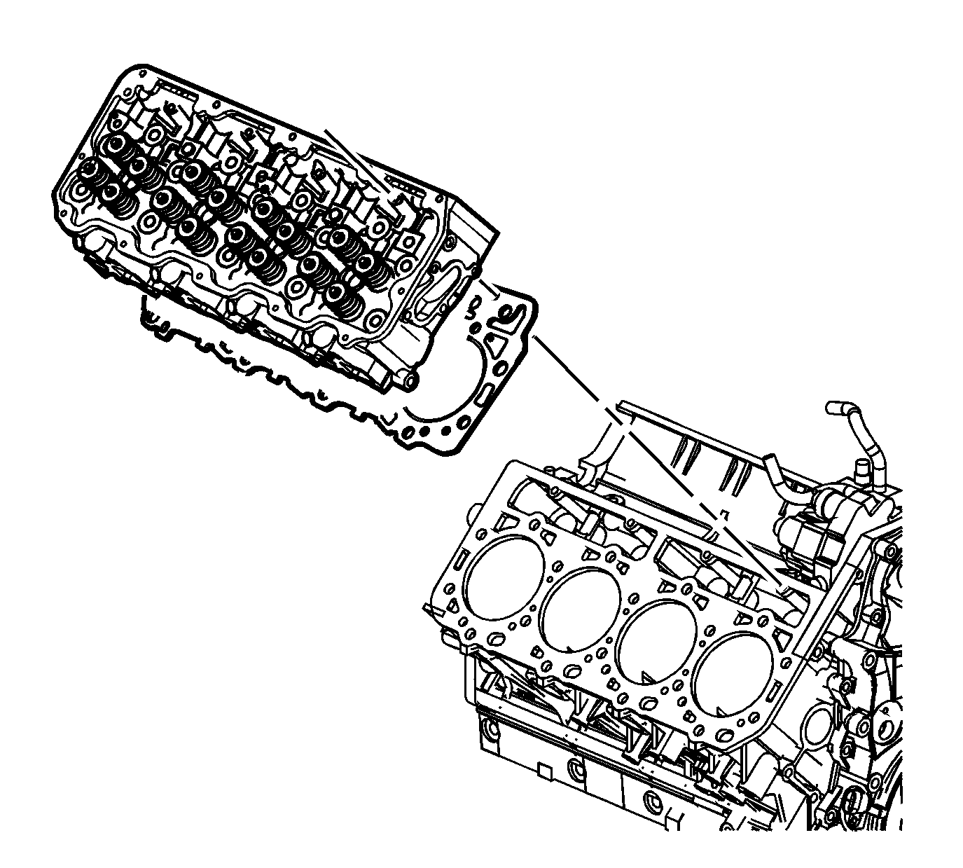
- Remove the cylinder head assembly.
- Remove and discard the cylinder head gasket.
- Clean the sealing surface of the engine block and the cylinder head.
- Clean the cylinder head bolt holes in the engine block.
- For service to the cylinder head refer to the following:
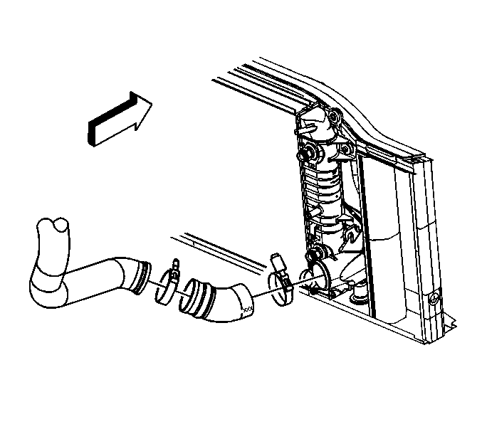
| 5.1. | Remove the clamp and hose from the charged air cooler. |
| 5.2. | Remove the charged air cooler outlet duct. |
Notice: Clean all dirt, debris, and coolant from the engine block cylinder head bolt holes. Failure to remove all foreign material may result in damaged threads, improperly tightened fasteners or damage to components.
| • | Refer to Cylinder Head Disassemble for the 6.6 L engine Unit Repair. |
| • | Refer to Cylinder Head Cleaning and Inspection for the 6.6 L engine Unit Repair. |
| • | Refer to Cylinder Head Assemble for the 6.6 L engine Unit Repair. |
Cylinder Head Gasket Grade
Gasket Grade | Projection Value | Gasket Thickness |
|---|---|---|
A (No hole) | Over 0.223 to less than 0.274 mm (0.0088 to less than 0.0108") | 0.90 to 1.00 mm (0.0354 to 0.0394") |
B (One hole) | Over 0.274 to less than 0.325 mm (0.0108 to less than 0.0128") | 0.95 to 1.05 mm (0.0374 to 0.0413") |
C (Two holes) | Over 0.325 to less than 0.376 mm (0.0128 to less than 0.0148") | 1.00 to 1.10 mm (0.0394 to 0.0433") |
Installation Procedure
- If the injector sleeve is pulled from the cylinder head when removing the injector, the injector sleeve installation procedure is as follows:
- Install the right cylinder head gasket of the correct grade selected.
- Install the right cylinder head assembly.
- Install the NEW cylinder head bolts.
- Tighten the cylinder head bolts in the following steps using the proper sequence.
- Tighten the M12 bolts a first pass to 50 N·m (37 lb ft).
- Tighten the M12 bolts a second pass to 80 N·m (59 lb ft)
- Tighten the M12 bolts a third pass to 60 degrees, using J 45059 .
- Tighten the M12 bolts a final pass to 60 degrees, using J 45059 .
- Tighten the M8 bolts to 25 N·m (18 lb ft).
- Install a new O-ring onto the fuel injector.
- Lubricate the O-ring with clean engine oil.
- Ensure the injector bore is clean and free from carbon.
- Install a new copper washer into the fuel injector bore in the cylinder head.
- Install the fuel injector bracket pin.
- If reusing the injectors, clean the injector tip of carbon. Do not clean with a wire brush.
- Install the fuel injector with fuel injector bracket.
- Install the fuel injector bracket bolt.
- Install the fuel injector return pipe assembly.
- Install the fuel injector return pipe to injector eye bolts and washers.
- Install the fuel return pipe to cylinder head eye bolts and washers.
- Install the valve rocker arm shaft assembly, pushrods, and valve bridges. Refer to Valve Rocker Arm, Shaft, and Push Rod Replacement .
- Install the glow plugs. Refer to Glow Plug Replacement - Bank 2 .
- Install the right exhaust manifold. Refer to Exhaust Manifold Replacement - Right Side .
- Install the lower right valve rocker arm cover. Refer to Valve Rocker Arm Cover Replacement - Upper Right Side .
- Install the upper right valve rocker arm cover. Refer to Valve Rocker Arm Cover Replacement - Upper Left Side
- Install the right intake manifold. Refer to Intake Manifold Replacement - Right Side .
- Install the right fuel rail assembly. Refer to Fuel Injection Fuel Rail Assembly Replacement - Bank 1 L.
- Install the thermostat housing crossover. Refer to Thermostat Housing Crossover Replacement .
- Install the turbocharger charged air cooler duct.
- Install the clamp and hose to the charged air cooler.
- Install the turbocharger. Refer to Turbocharger Replacement .
- Install the right fender wheelhouse inner panel (1).
- Connect the battery negative cable. Refer to Battery Negative Cable Disconnection and Connection .
- Fill the cooling system. Refer to Cooling System Draining and Filling .
- Road test the vehicle for normal operation.
- Inspect for coolant, oil, or exhaust leaks.
Important:
|
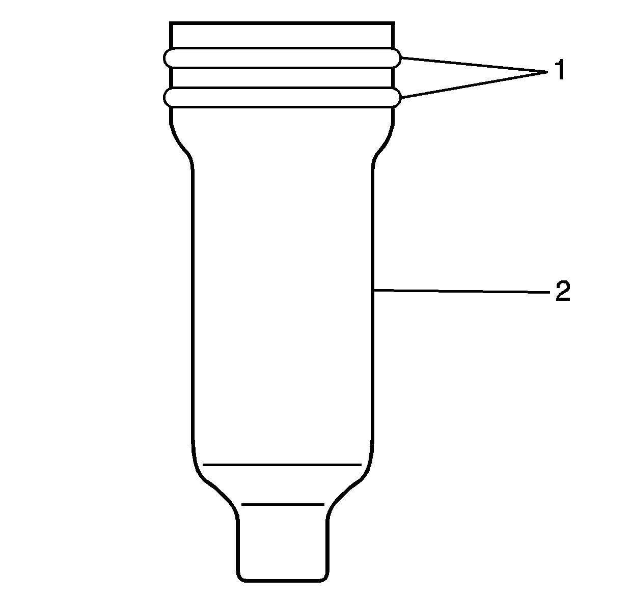
| 1.1. | Set the new injector sleeve gaskets (1) to the injector sleeve (2). |
| 1.2. | Apply sealant (LOCTITE 272 or equivalent) to the lower sealing area of injector sleeve. |
Notice: The left and right cylinder head gaskets are not interchangeable. Improper placement of the cylinder head gasket will block coolant and oil passages. Blocked coolant and oil passages will cause severe engine damage.
Notice: Refer to Fastener Notice in the Preface section.
Notice: This component uses bolts with a preapplied molybdenum disulfide coating for thread lubrication. Do not remove the coating or use any additional lubricant. Improperly lubricated threads will adversely affect the bolt torque and clamp load. Improper bolt torque and clamp load can lead to engine damage.
Tighten
Tighten
Tighten the fuel injector bracket bolt to 50 N·m (37 lb ft).
Tighten
Tighten the fuel injector return pipe to injector eye bolts to 15 N·m (133 lb in).
Tighten
Tighten the fuel injector return pipe to cylinder head eye bolts to 15 N·m (133 lb in).
Tighten
Tighten the charged air cooler clamp to 6 N·m (53 lb in).
