For 1990-2009 cars only
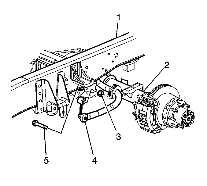
Stabilizer Shaft Link Replacement 35 Series
Removal Procedure
- Raise and support the vehicle. Refer to Lifting and Jacking the Vehicle .
- Remove the stabilizer shaft link nut (5) from the frame (1).
- Remove the stabilizer link nut from the stabilizer shaft (4).

Installation Procedure
- Install the stabilizer shaft link to the frame (1) and to the stabilizer shaft and install the retaining nuts (5).
- Lower the vehicle.
Notice: Refer to Fastener Notice in the Preface section.

Tighten
| • | Tighten the stabilizer shaft link bolt to the frame (1) to 95 N·m (70 lb ft). |
| • | Tighten the stabilizer shaft link to the stabilizer shaft to 145 N·m (107 lb ft). |
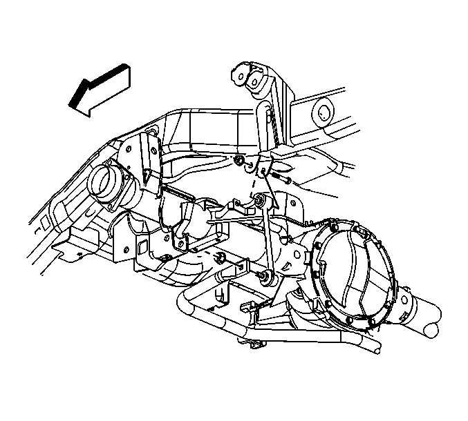
Stabilizer Shaft Link Replacement 15 Series
Removal Procedure
- Raise and support the vehicle. Refer to Lifting and Jacking the Vehicle .
- Remove the stabilizer shaft link nut and bolt from the frame bracket.
- Remove the stabilizer shaft link nut from the ball stud.
- Remove the stabilizer shaft link.

Installation Procedure
- Install the stabilizer shaft link.
- Install the stabilizer shaft link nut to the ball stud.
- Install the stabilizer shaft link nut and bolt to the frame bracket.
- Tighten the link to frame bracket nut to 65 N·m (48 lb ft).
- Tighten the ball stud to stabilizer shaft nut to 65 N·m (48 lb ft).
- Tighten the stabilizer shaft link to the stabilizer shaft to 145 N·m (107 lb ft).
- Lower the vehicle.

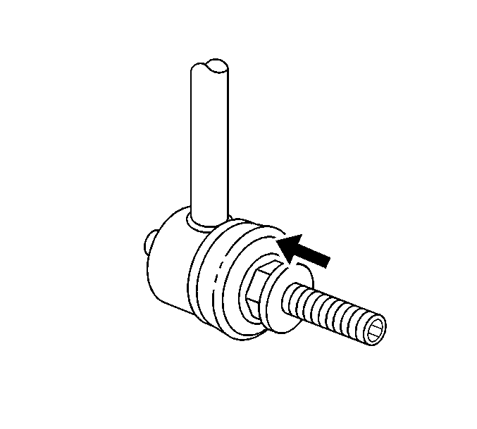
Important: When tightening the lower link nut verify that the inner jam nut bottoms out on the ball stud.

Notice: Refer to Fastener Notice in the Preface section.

Tighten
