Removal Procedure
- Remove the negative battery cable.
- Thoroughly wash all contaminants from around the EHCU.
- Disconnect the 3 electrical harness connectors from the electronic brake control module (EBCM).
- Disconnect the 5 brake lines from the brake pressure modulator valve (BPMV). When looking at the brake pipe port face of the BPMV, the ports are assigned as follows:
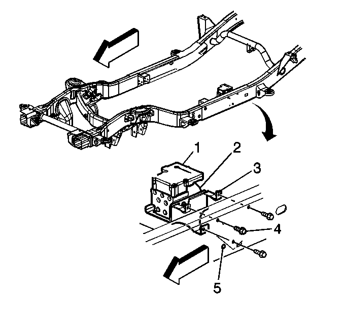
- Remove the bolts (4) securing the EHCU mounting bracket (3) to the frame rail (5).
- Remove the EHCU (1) from the vehicle.
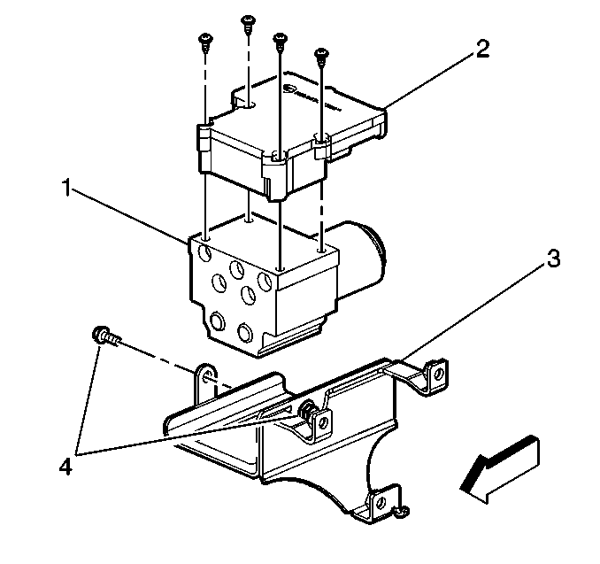
- Remove the bolts (4) securing the BPMV mounting bracket (3) to the BPMV (1).
- Disconnect the 2 way ABS pump motor connector.
- Remove the T-25 TORX® bolts from the EBCM (2).
- Remove the EBCM (2) from the BPMV (1). Removal may require a light amount of force.
- Clean the EBCM to BPMV mounting surfaces with a clean cloth.
Caution: Unless directed otherwise, the ignition and start switch must be in the OFF or LOCK position, and all electrical loads must be OFF before servicing any electrical component. Disconnect the negative battery cable to prevent an electrical spark should a tool or equipment come in contact with an exposed electrical terminal. Failure to follow these precautions may result in personal injury and/or damage to the vehicle or its components.

Important: The area around the electric hydraulic control unit (EHCU) MUST be free from loose dirt to prevent contamination of disassembled ABS components.
Important: Make sure that brake lines are tagged and kept in order for proper reassembly.
| • | Upper Left--Left Front Output |
| • | Upper Middle--Right Front Output |
| • | Upper Right--Rear Output |
| • | Lower Left--Master Cylinder Secondary/Front Input |
| • | Lower Right--Master Cylinder Primary/Front Input |

Important:
• Do not use a tool to pry the EBCM or the BPMV. Excessive force will damage the EBCM. • Do not reuse the EBCM mounting bolts. Always install new bolts.
Installation Procedure
- Install the EBCM (2) onto the BPMV (1).
- Install the four EBCM bolts.
- Connect the 2 way ABS pump motor connector to the EBCM.
- Install the BPMV (1) to BPMV bracket (3).
- Install the BPMV to bracket retaining bolts (4).
- Install the EHCU (1, 2) to the vehicle frame (5).
- Connect the two electrical harness connectors to the EBCM (1).
- Install the 5 brake pipes to the BPMV (6).
- Connect the negative battery cable.
- Bleed the brake system. Refer to Antilock Brake System Automated Bleed Procedure .

Important: Do not use RTV or any other type of sealant on the EBCM gasket or mating surfaces.
Notice: Refer to Fastener Notice in the Preface section.
Important: Do not reuse the old mounting bolts. Always install new bolts with the new BPMV.
Tighten
Tighten the four bolts to 5 N·m (39 lb in) in an X-pattern.
Tighten
Tighten the bolts to 9 N·m (7 lb ft).

Tighten
Tighten the three EHCU bracket bolts (4) to 25 N·m (18 lb ft).
Important: The brake pipes are held in the proper place by a frame mounted plastic bracket. Ensure the brake pipes stay in the correct place for proper reassembly.
Tighten
Tighten the brake pipe fittings to 30 N·m (22 lb ft).
