Special Tools
| • | J 21366 Converter Holding Strap |
| • | J 41798 Engine Lifting Brackets |
Removal Procedure
- Open the hood.
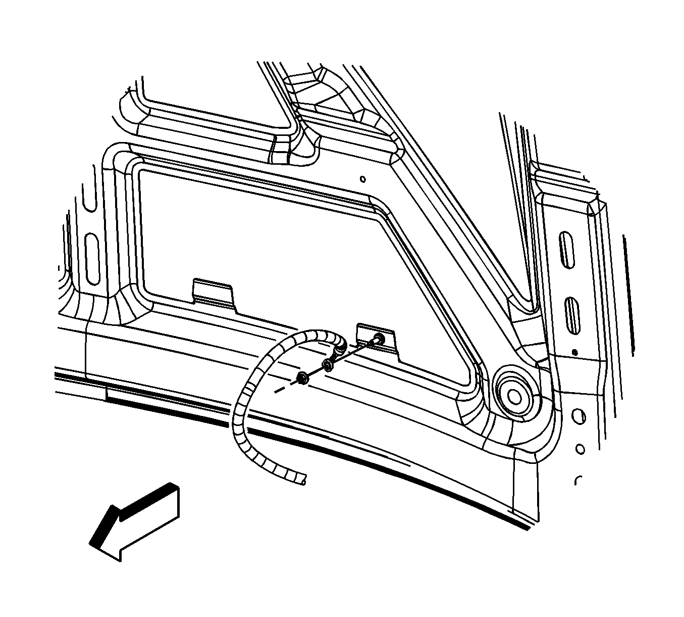
- Remove the ground strap nut at the hood stud.
- Remove the ground strap from the stud.
- Assemble 2 sets of the following: an M6 bolt, 2 each 19.05 mm (0.75 in) flat washers and an M6 nut.
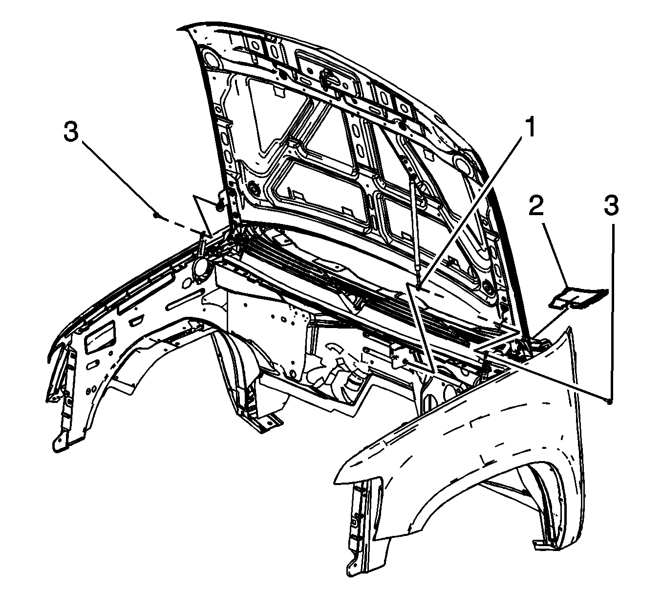
- Release the retainer securing the hood strut rod to the hood strut bracket stud.
- Remove the hood strut rod (1) from the stud.
- Remove the air inlet grille end caps (2), lift the end cap up in order to disengage the retainers. (left side shown, right side similar).
- Have an assistant support the hood.
- Remove the hood hinge bolts (3) and set aside.
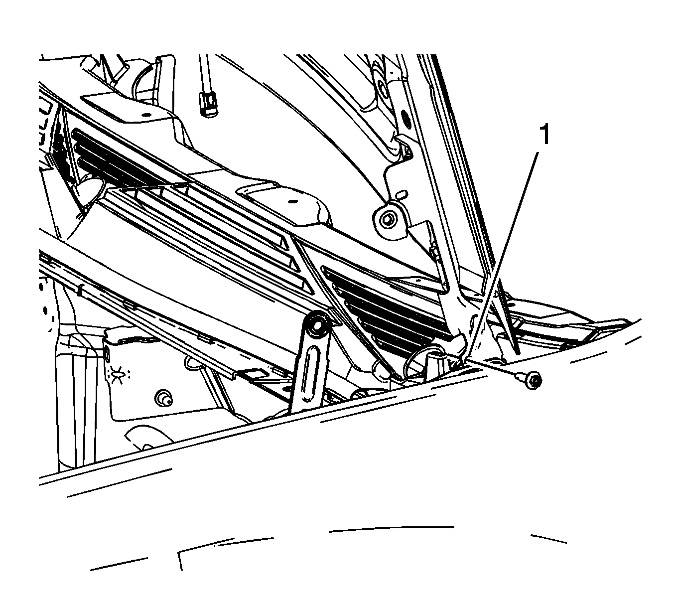
- Raise the hood until the service position notch (1) in the upper hinge is reached.
- Install the 2 sets of the M6 bolts to both the left and right side service notches and tighten finger tight.
- Lower the hood until the bolts rest against the lower hinge, tighten the bolts to secure the hood.
- The hood is now set in the service position.
- Remove the hood latch. Refer to Hood Primary and Secondary Latch Replacement.
- Remove the front end upper tie bar. Refer to Front End Upper Tie Bar Replacement.
- Remove the intake manifold. Refer to Intake Manifold Replacement.
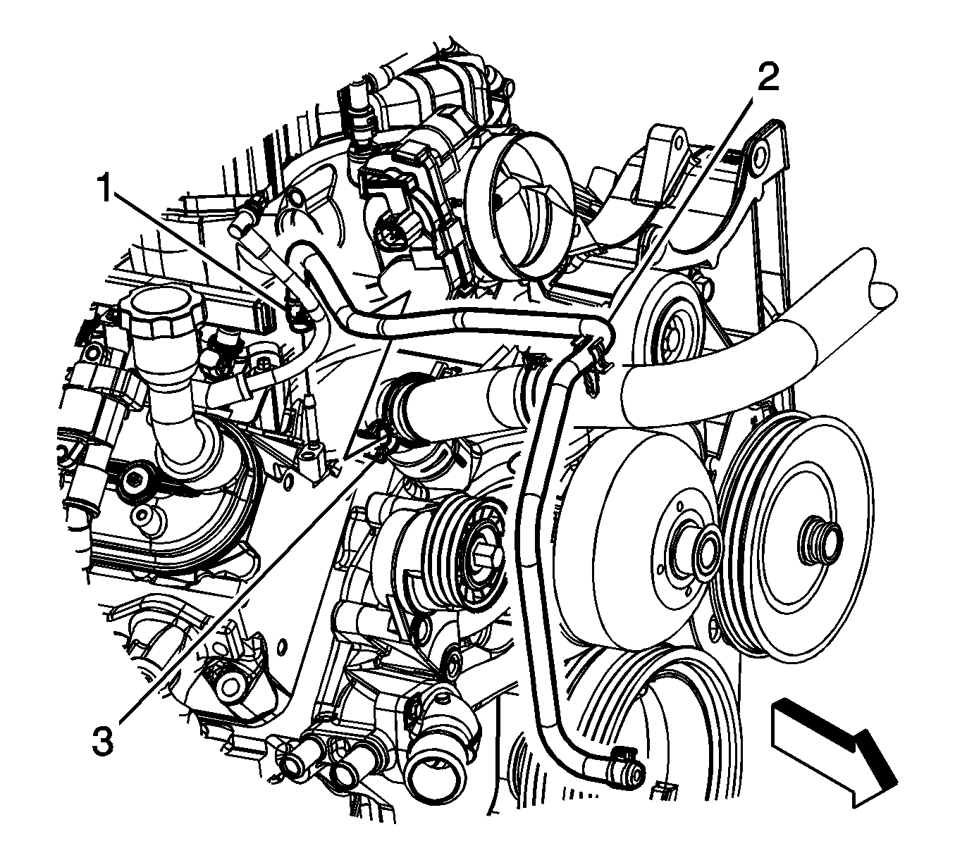
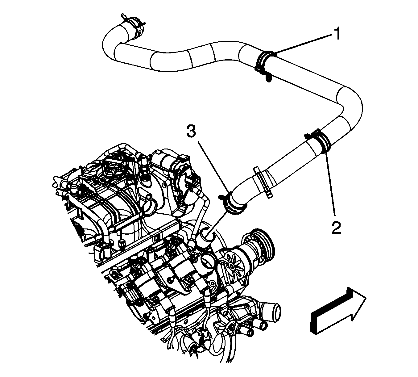
- Remove the radiator vent inlet hose (2) from the radiator inlet hose clip (3).
- Reposition the radiator vent inlet hose clamp (1) at the air bleed pipe.
- Remove the radiator vent inlet hose (2) from the air bleed pipe and reposition.
- Reposition the radiator inlet hose clamp (3) at the water pump.
- Remove the radiator inlet hose from the water pump.
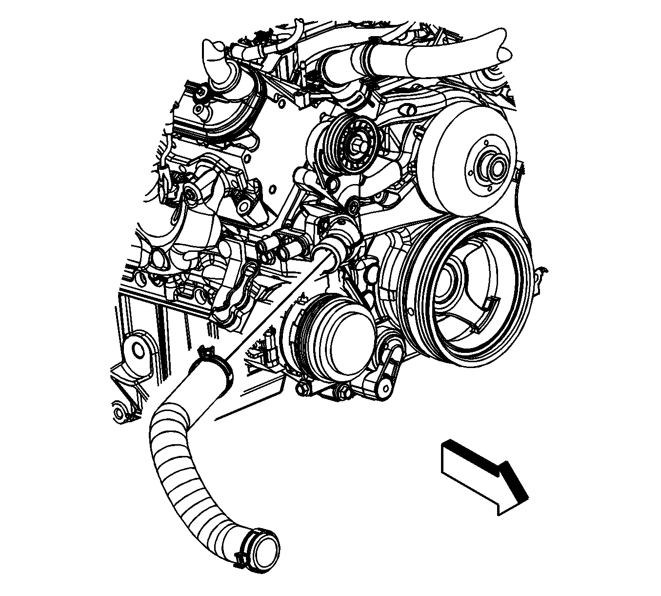
- Reposition the radiator outlet hose clamp at the water pump.
- Remove the radiator outlet hose from the water pump.
- Remove the heater hoses. Refer to Heater Inlet Hose Replacement and Heater Outlet Hose Replacement.
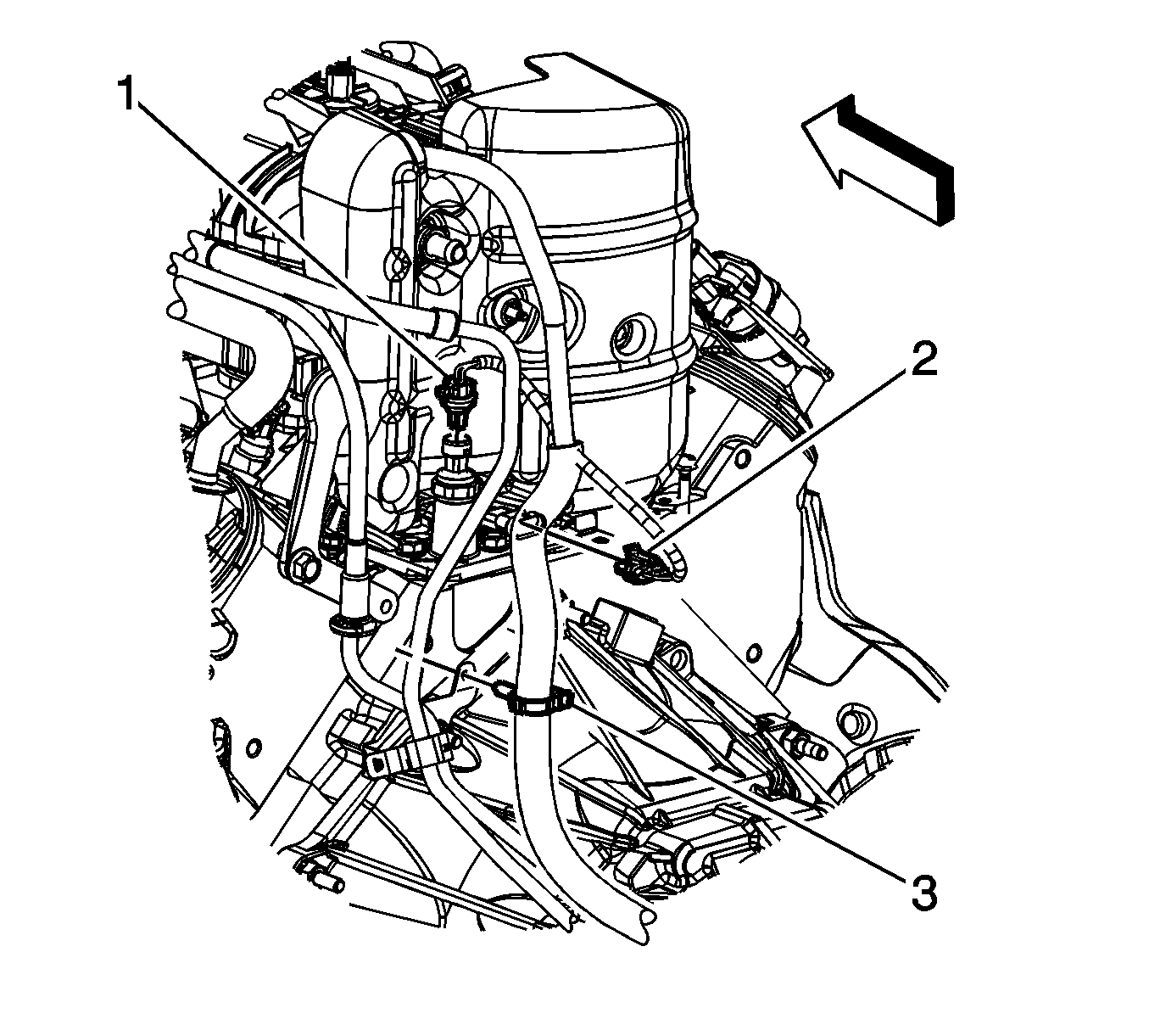
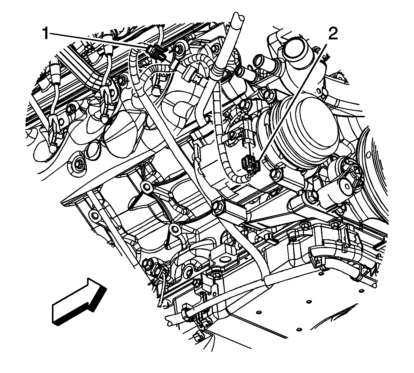
- Disconnect the engine harness electrical connector (1) from the oil pressure sensor.
- Disconnect the engine harness electrical connector (2) from the lifter oil manifold.
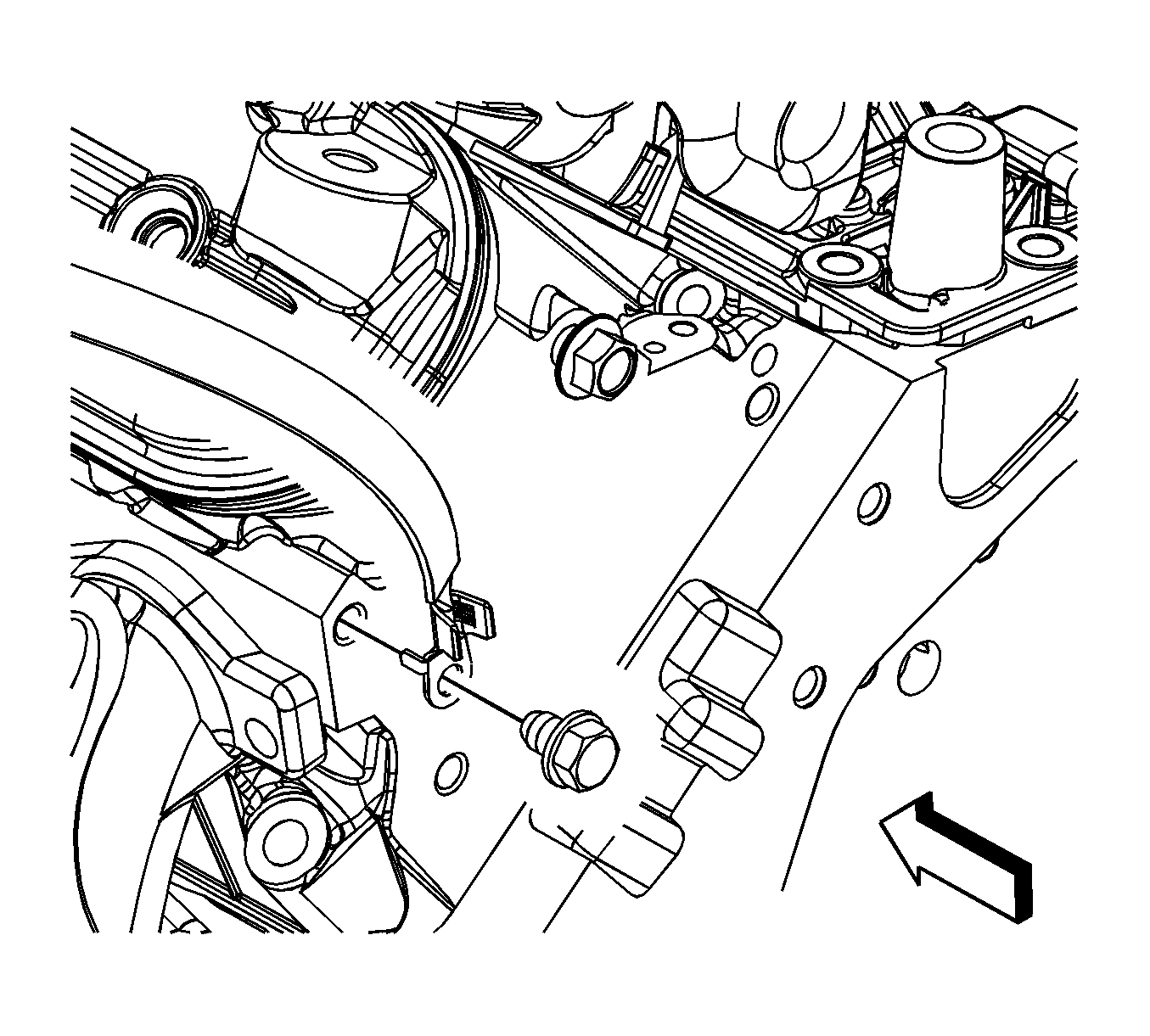
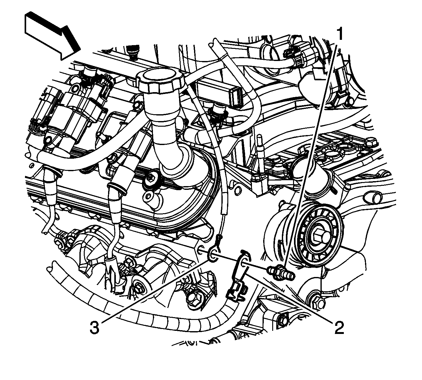
- Remove the engine ground strap bolt from the rear of the left cylinder head and cowl and reposition.
- Remove the negative battery cable stud (1) from the right cylinder head.
- Remove the negative battery cable terminal (2) and the engine harness ground (3) from the right cylinder head.
- Raise and support the vehicle. Refer to Lifting and Jacking the Vehicle.
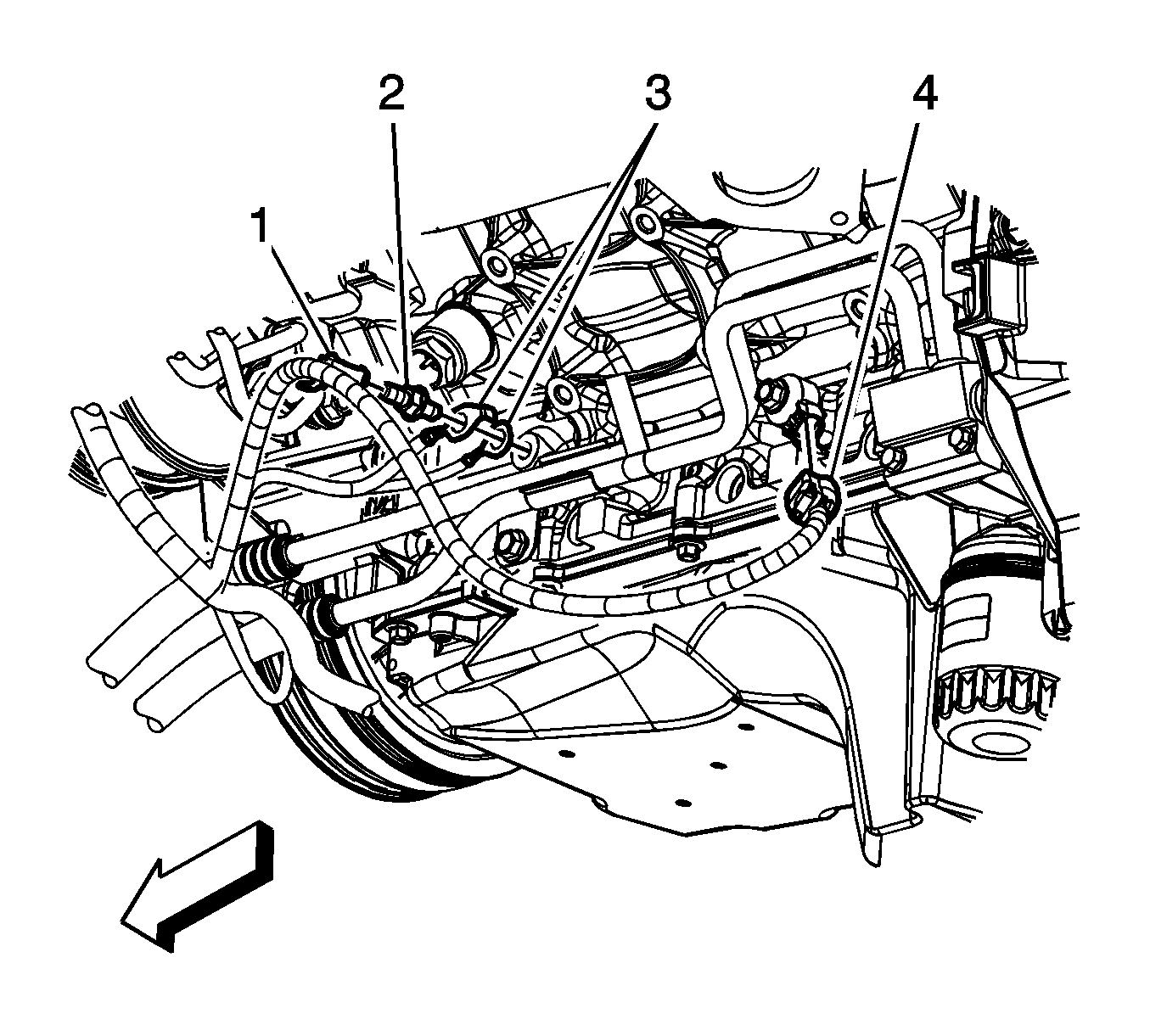
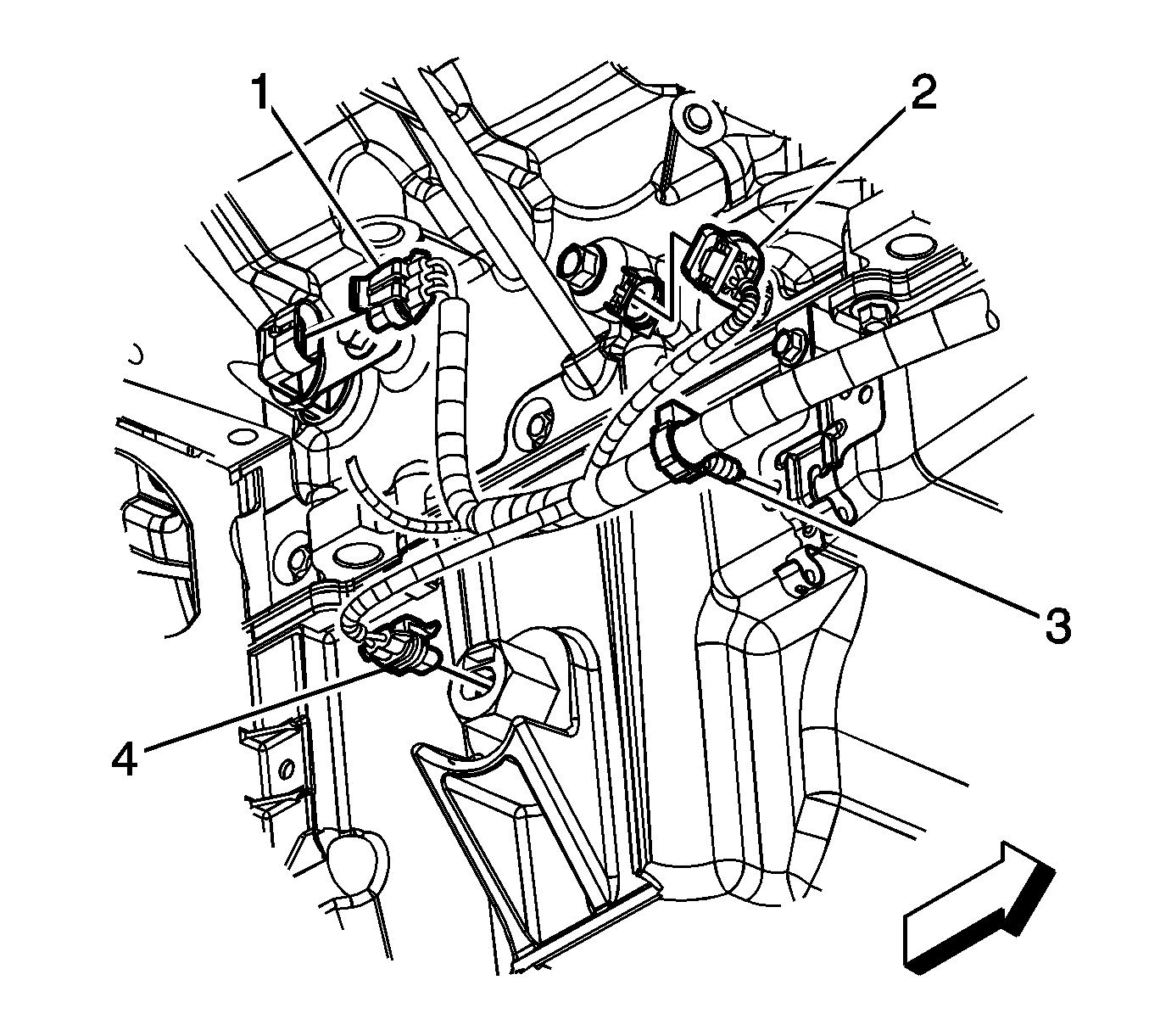
- Remove the engine harness clip (1) from the ground stud.
- Remove the engine harness ground stud (2) from the engine block.
- Remove the engine harness grounds (3) from the engine block.
- Disconnect the engine harness electrical connector (4) from the knock sensor.
- Remove the transmission oil cooler line clip bolt from the oil pan, if equipped.
- Disconnect the engine harness electrical connector (1) from the camshaft position (CMP) sensor wire harness.
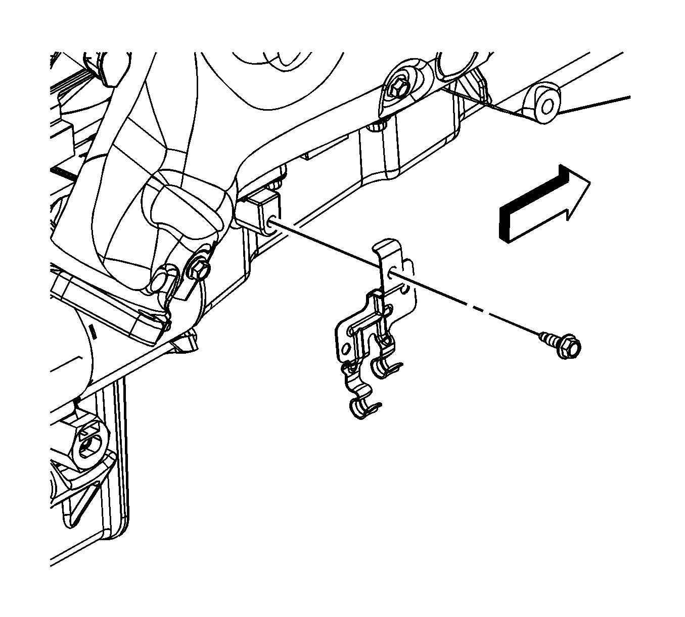
- Remove the battery cable channel bolt (2).
- Slide the channel pin (3) out of the oil pan tab.
- Disconnect the engine harness electrical connector (1) from the A/C refrigerant pressure sensor.
- Remove the starter motor. Refer to Starter Motor Replacement.
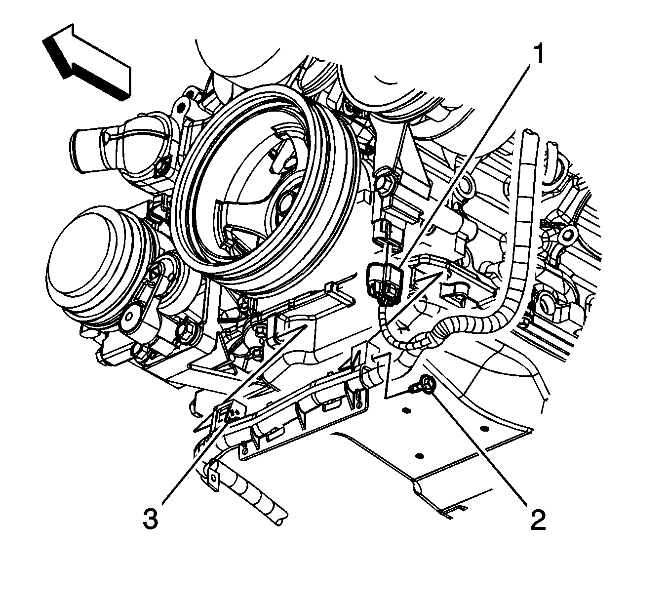
- Disconnect the engine harness electrical connector (1) from the crankshaft position (CKP) sensor.
- Disconnect the engine harness electrical connector (2) from the knock sensor.
- Disconnect the engine harness electrical connector (4) from the oil level sensor.
- Remove the engine harness clip (3) from the transmission oil cooler line bracket.
- Disconnect the coolant heater cord from the coolant heater, if equipped.
- Lower the vehicle.
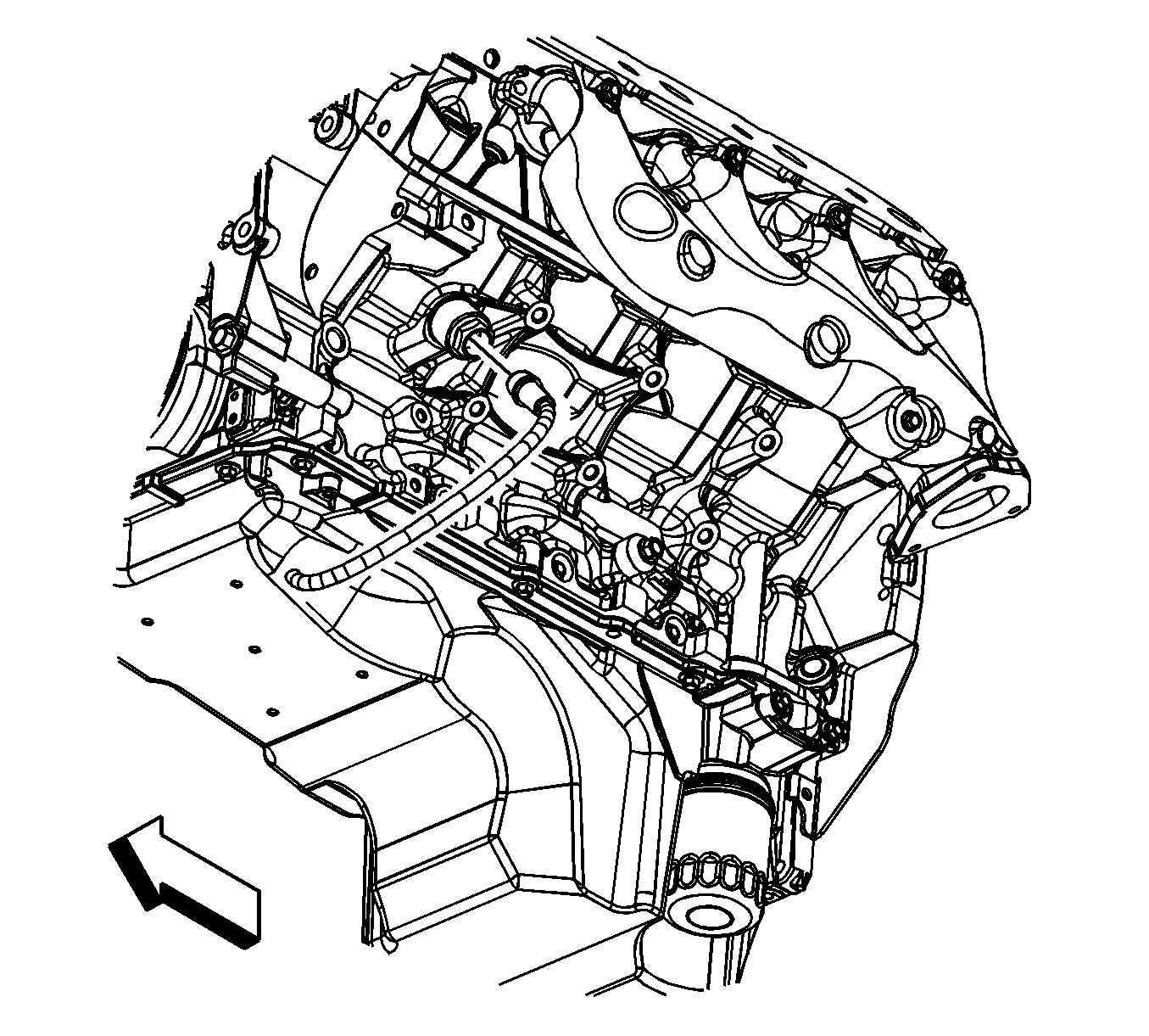
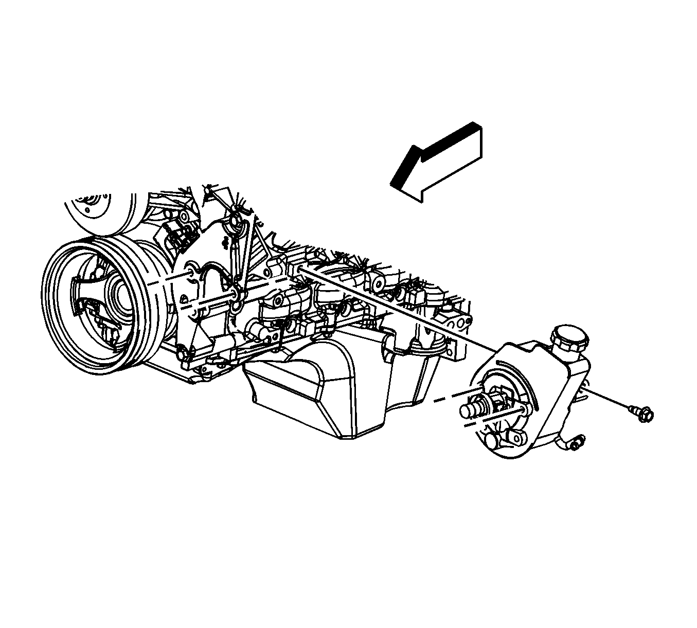
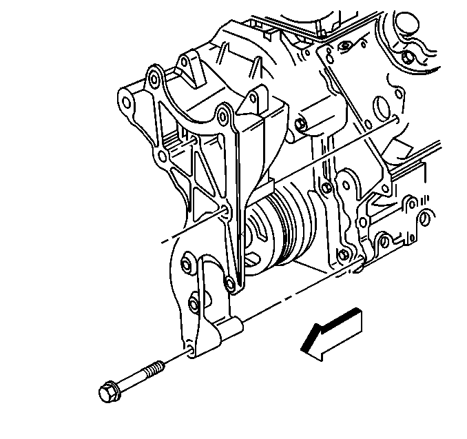
- Remove the rear power steering pump-to-engine block bolt (1500 series shown, 2500 series similar).
- Remove the generator bracket bolts.
- Position the generator bracket (with power steering pump) aside.
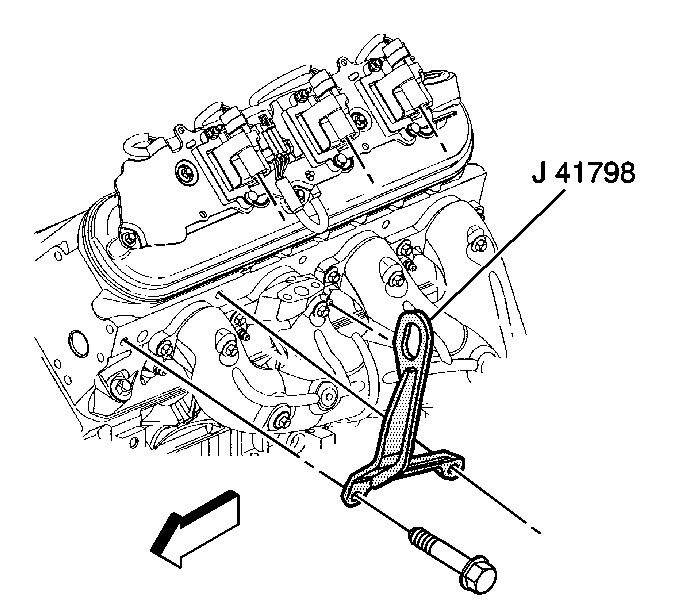
- Remove the ignition coil, as required for the proper fit of the J 41798 Engine Lift Bracket before lifting the engine. Refer to Ignition Coil Replacement.
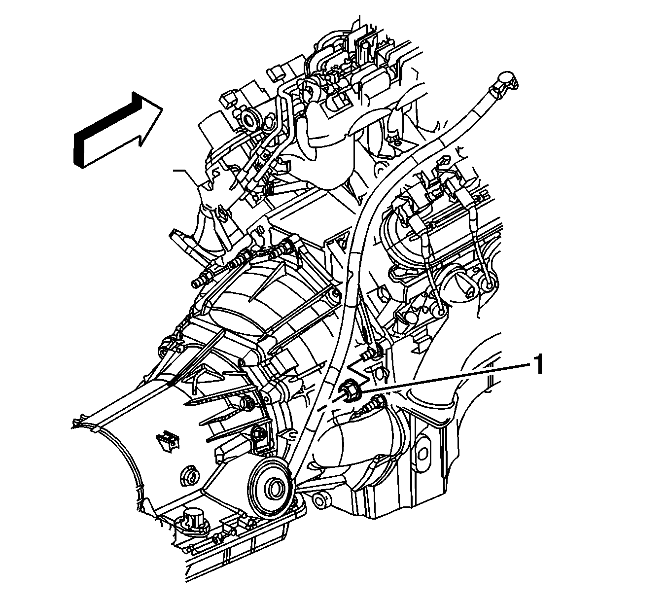
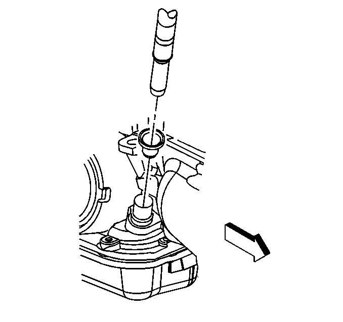
- Remove the transmission oil level indicator tube nut (1).
- Remove the transmission oil level indicator tube.
- Install the J 41798 Engine Lift Bracket to the cylinder heads.
- For 1500 series vehicles with a 4.8L engine, remove the left and right engine mount to frame bolts (1).
- For 1500 series vehicles with a 5.3L, 6.0L, or 6.2L engines, remove the left and right engine mount to frame bolts (1).
- For 2500 series vehicles with a 5.3L, 6.0L, or 6.2L engines, remove the left and right engine mount to engine mount bracket bolts (1).
- Raise the vehicle.
- Remove the engine shield bolts and shield.
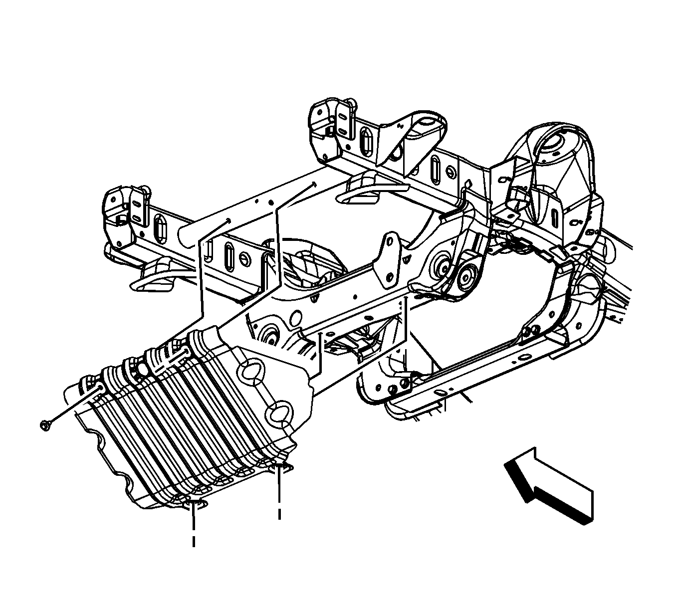
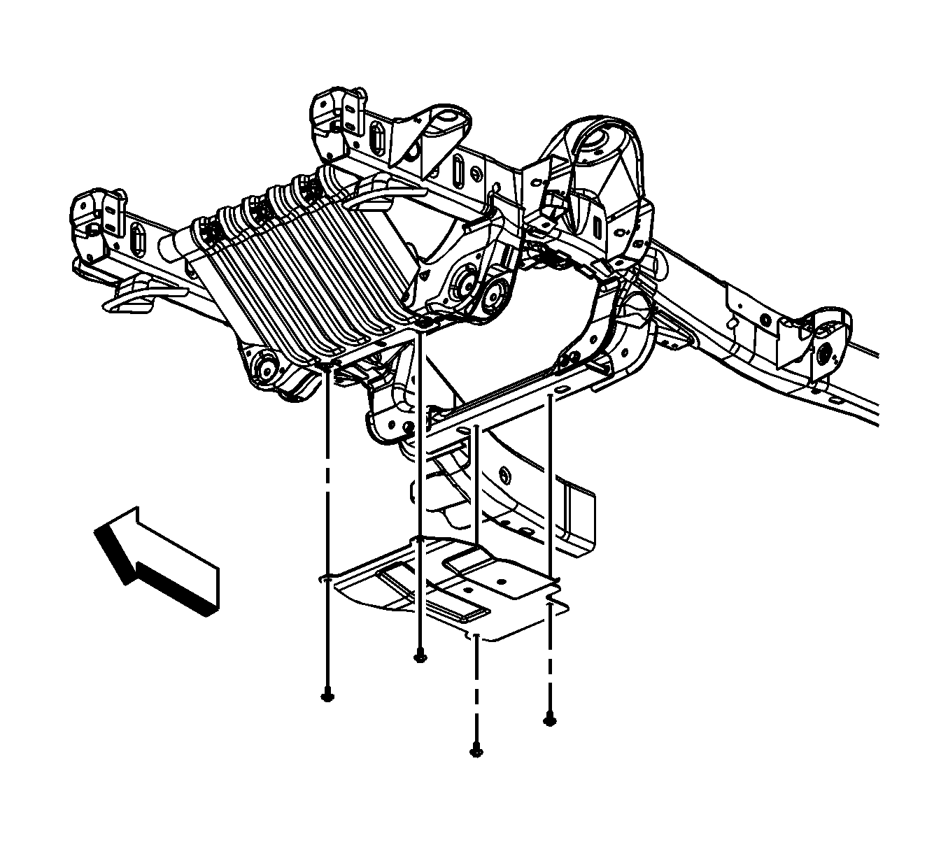
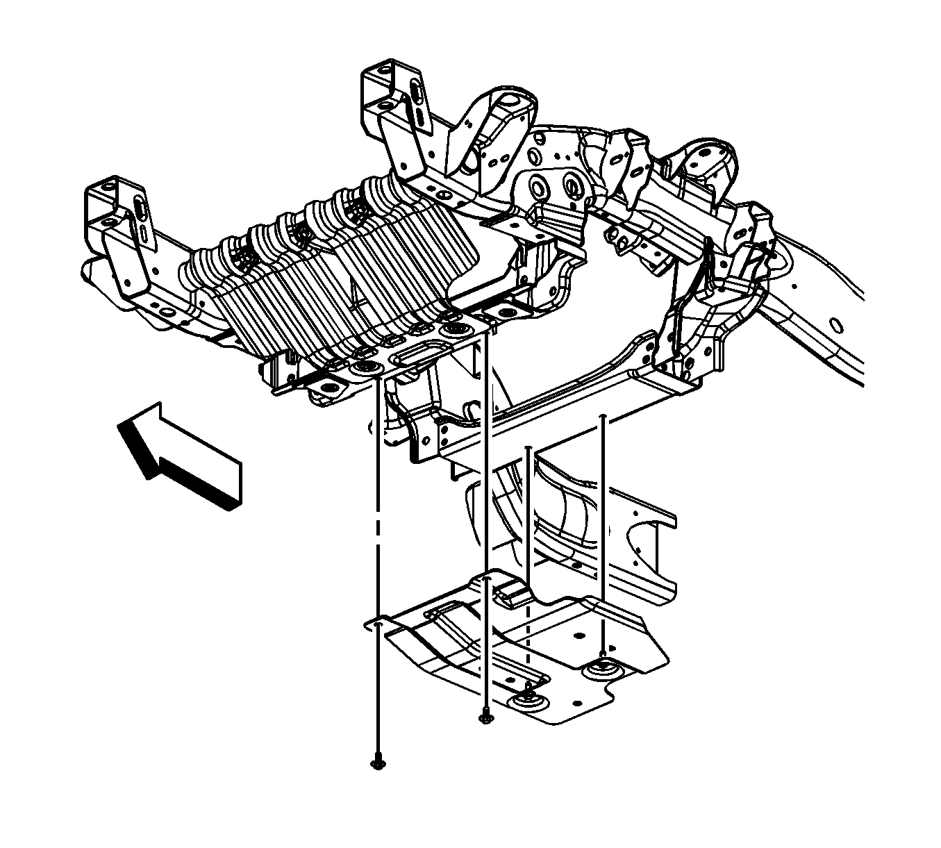
- For 1500 series vehicles, remove the oil pan skid plate bolts and plate, if equipped.
- For 2500 series vehicles, remove the oil pan skid plate bolts and plate, if equipped.
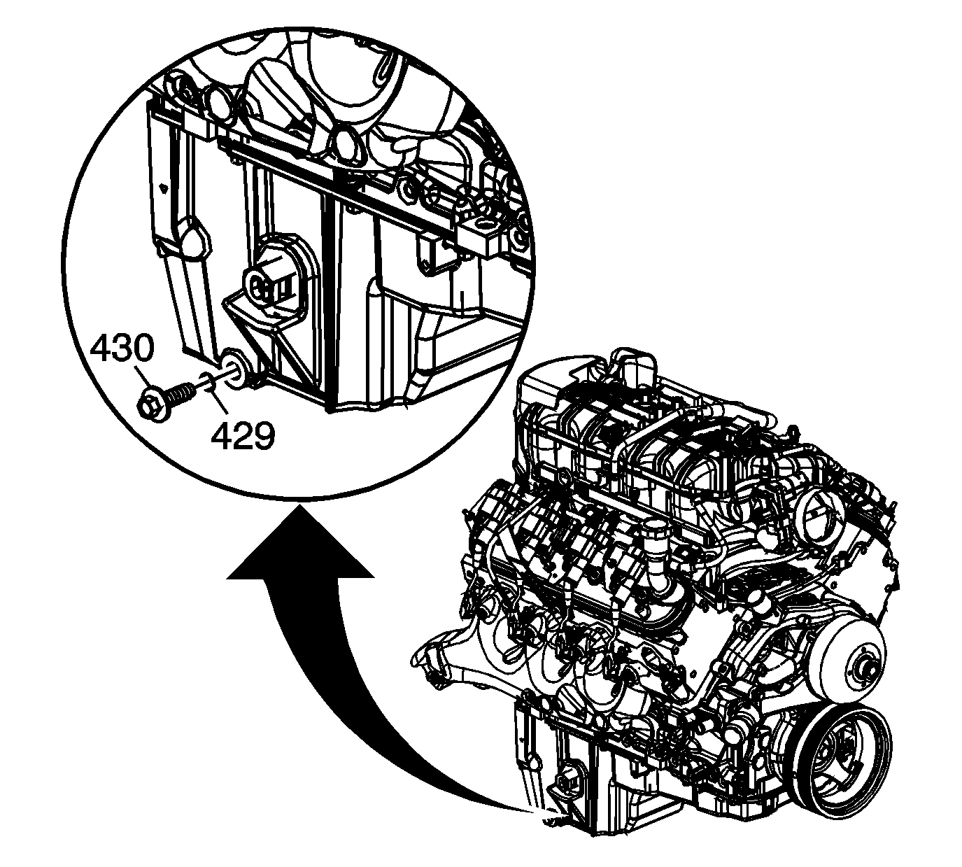
- Place a suitable drain pan under the oil pan drain plug.
- Remove the oil pan drain plug (430).
- Allow the oil to drain completely.
- Reinstall and tighten the oil pan drain plug.
- Remove the catalytic converter. Refer to Catalytic Converter Replacement or Three-Way Catalytic Converter Replacement
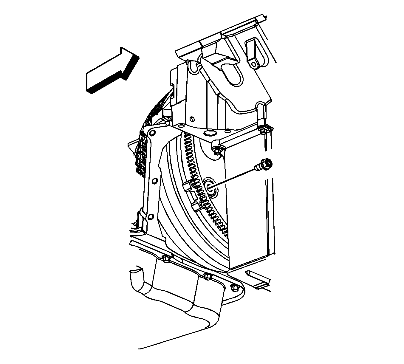
- Remove the flywheel to torque converter bolts.
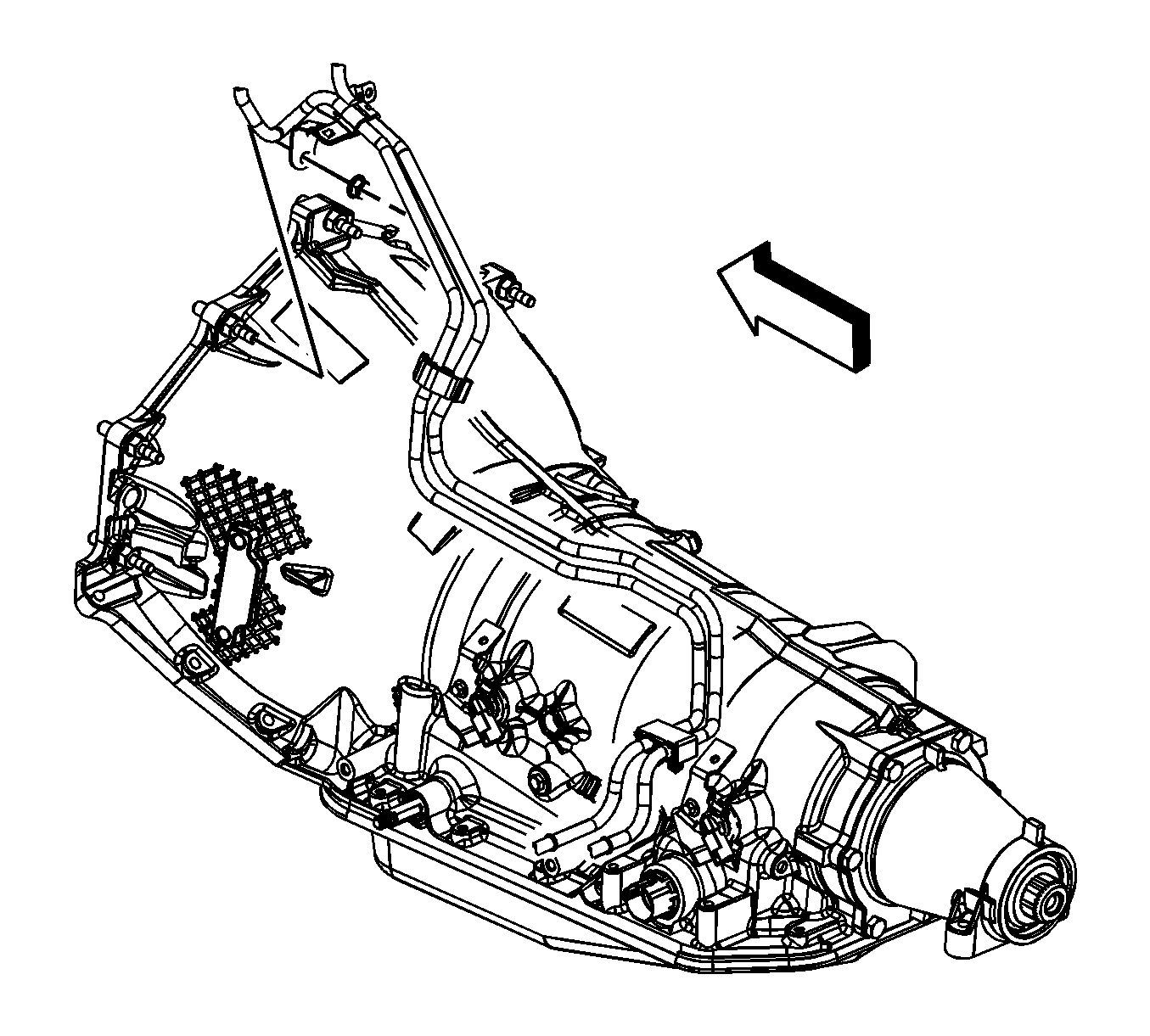
- Remove the fuel/evaporative emission (EVAP) pipe bracket nut from the transmission stud (typical installation shown).
- Remove the fuel/EVAP pipe bracket from the stud. Reposition the bracket out of the way.
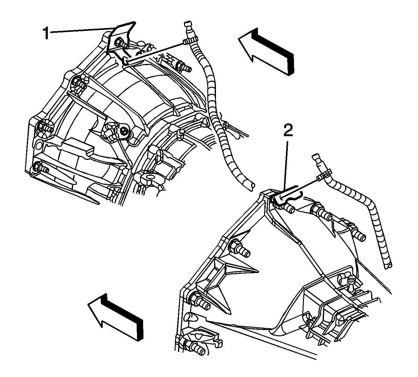
- For the 4L80-E automatic transmission, remove the transfer case vent hose bracket (1) nut from the stud, if equipped.
- For the 4L60-E/4L70-E/6L80-E automatic transmission, remove the transfer case vent hose bracket (2) nut from the stud, if equipped.
- Reposition the transfer case vent hose bracket and hose out of the way, if equipped.
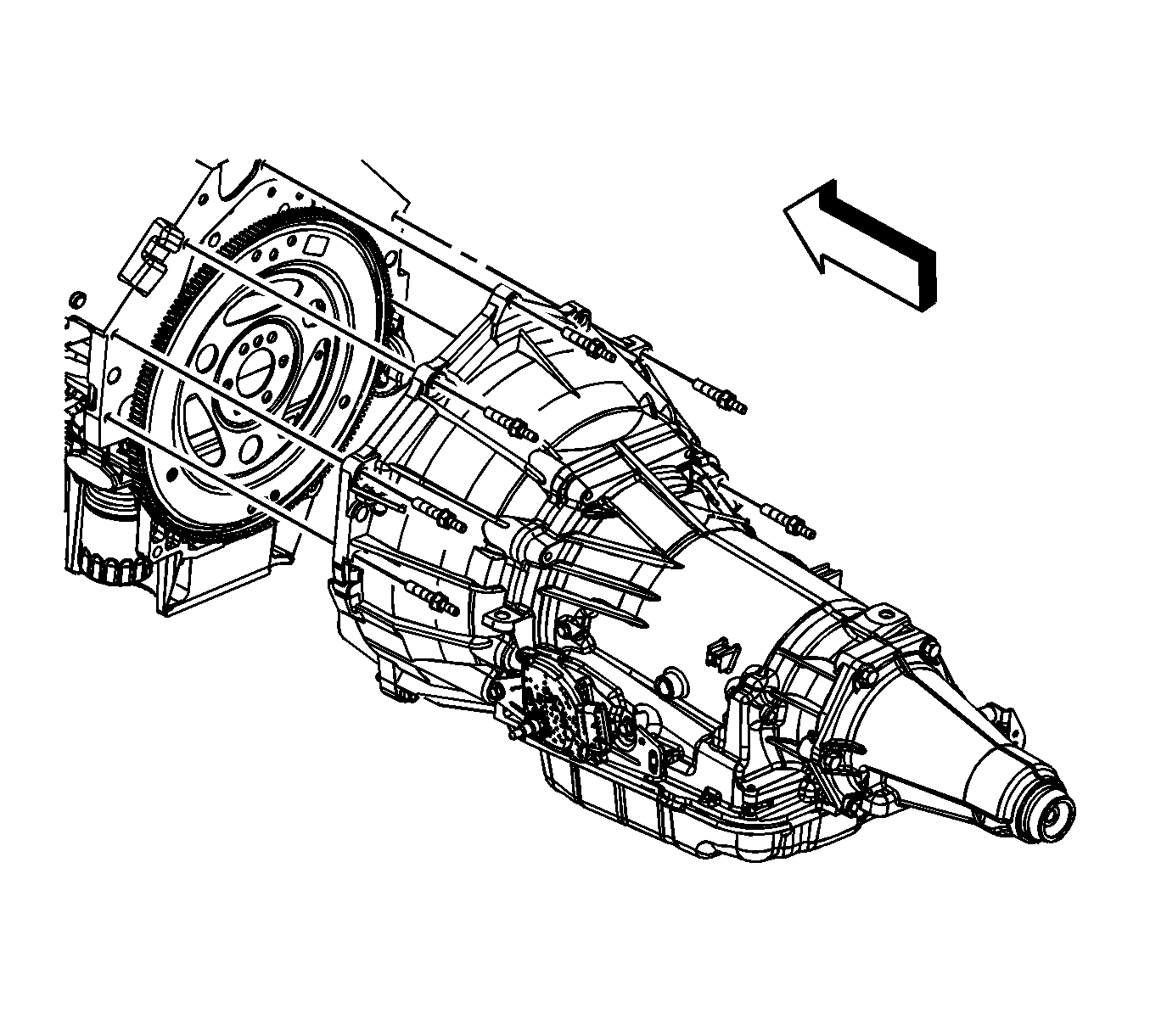
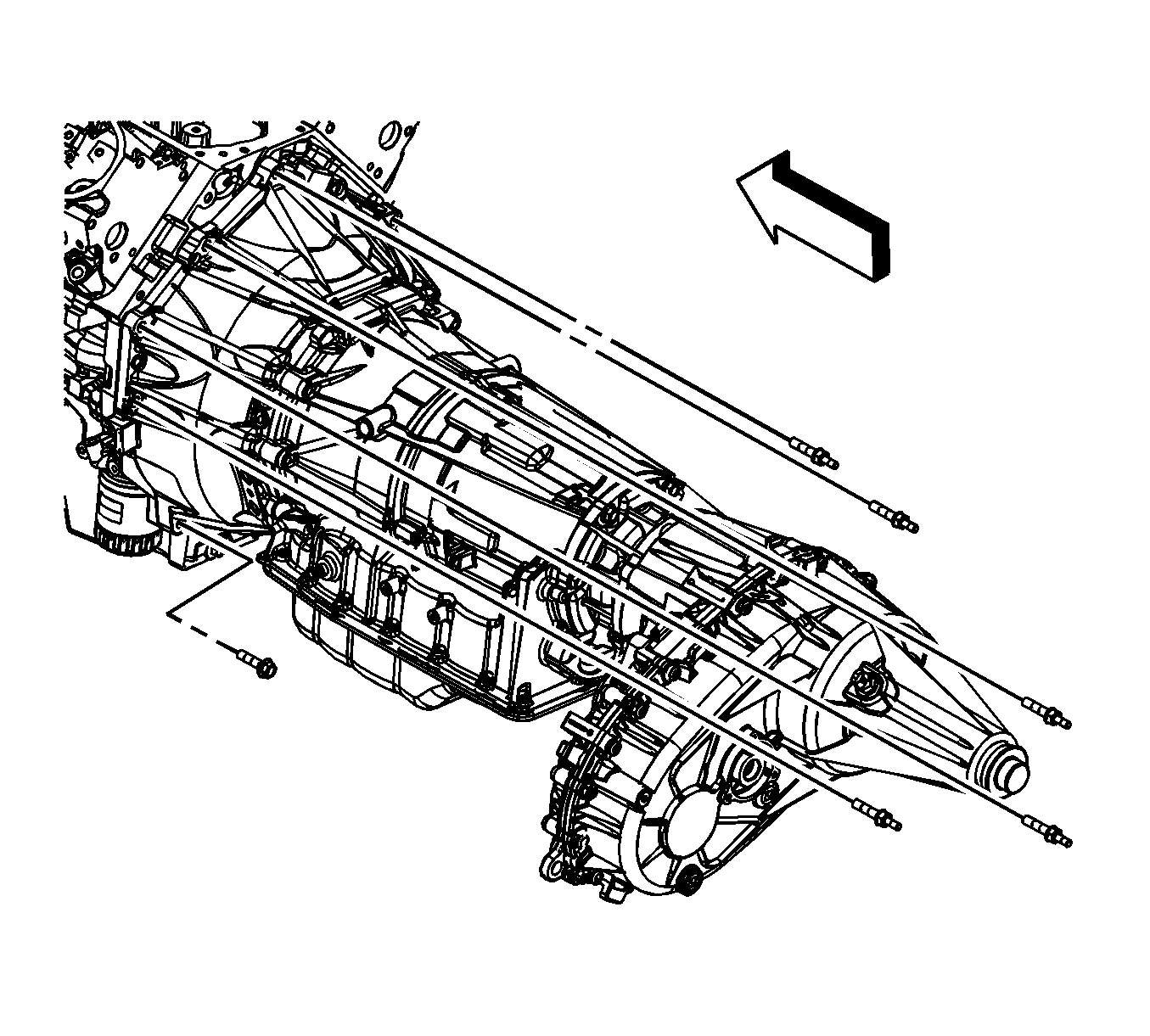
- If equipped with the 4L60-E/4L70-E automatic transmission, remove the transmission bolts/studs.
- If equipped with the 4L80-E automatic transmission, remove the transmission bolts/studs.
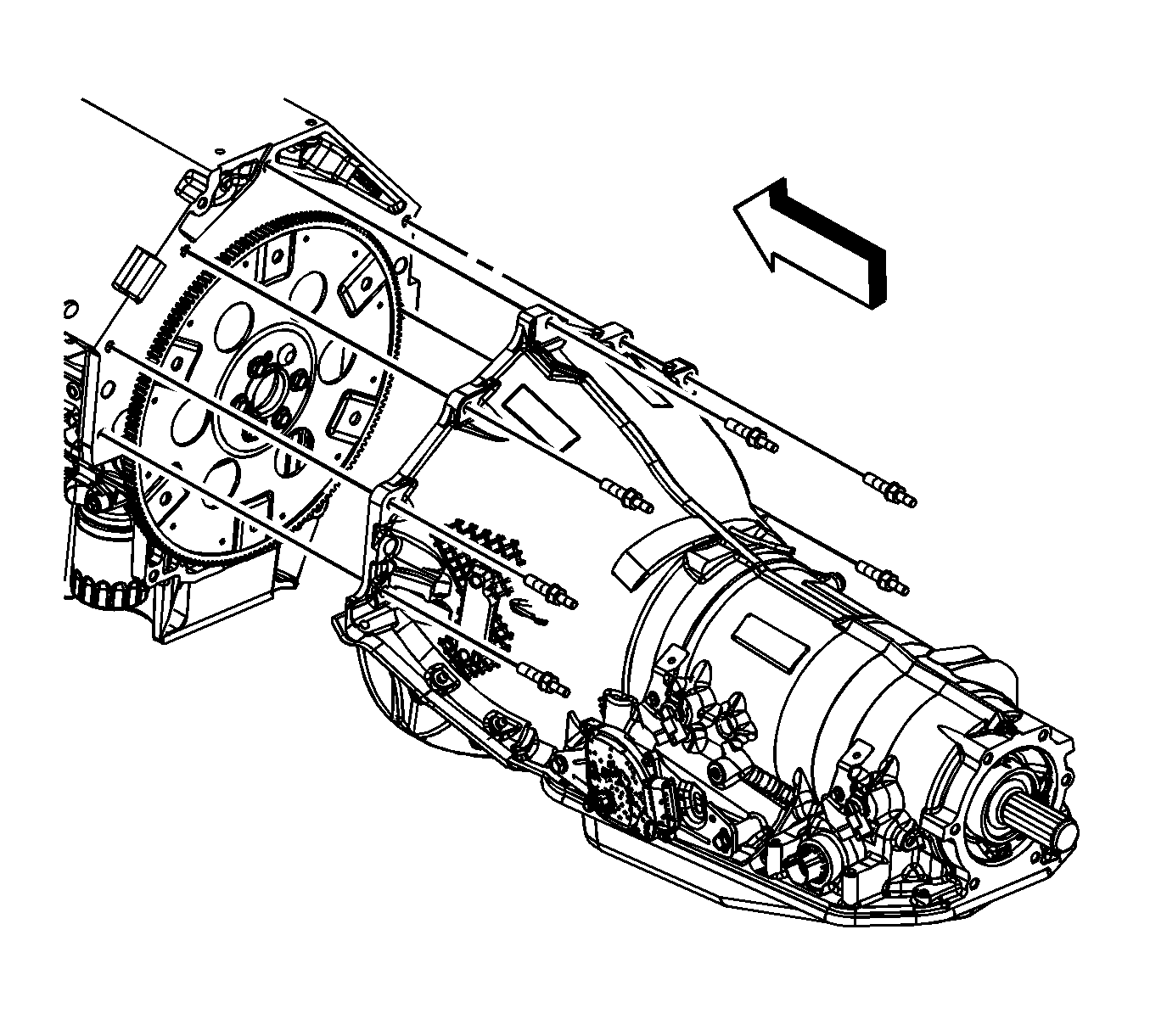
- If equipped with the 6L80-E automatic transmission, remove the transmission bolts/studs.
- Lower the vehicle.
- Position and install an engine hoist to the J 41798 Engine Lift Bracket .
- Install a floor jack under the transmission for support.
- Remove the engine from the vehicle.
- Install the J 21366 Converter Holding Strap to the transmission in order to hold the torque converter.
- Position and install the engine onto an engine stand.
- Remove the engine hoist. from the J 41798 Engine Lift Bracket .
- Remove the J 41798 from the engine.
Note: There is a positive stop which limits the hood from being opened too far.
Caution: Refer to Fastener Caution in the Preface section.
Tighten
Tighten the bolts to 20 N·m (15 lb ft).
Caution: Refer to Fastener Caution in the Preface section.
Tighten
| • | Tighten the M8 engine lift bracket bolts to 25 N·m (18 lb ft). |
| • | Tighten the M10 engine lift bracket bolts to 50 N·m (37 lb ft). |
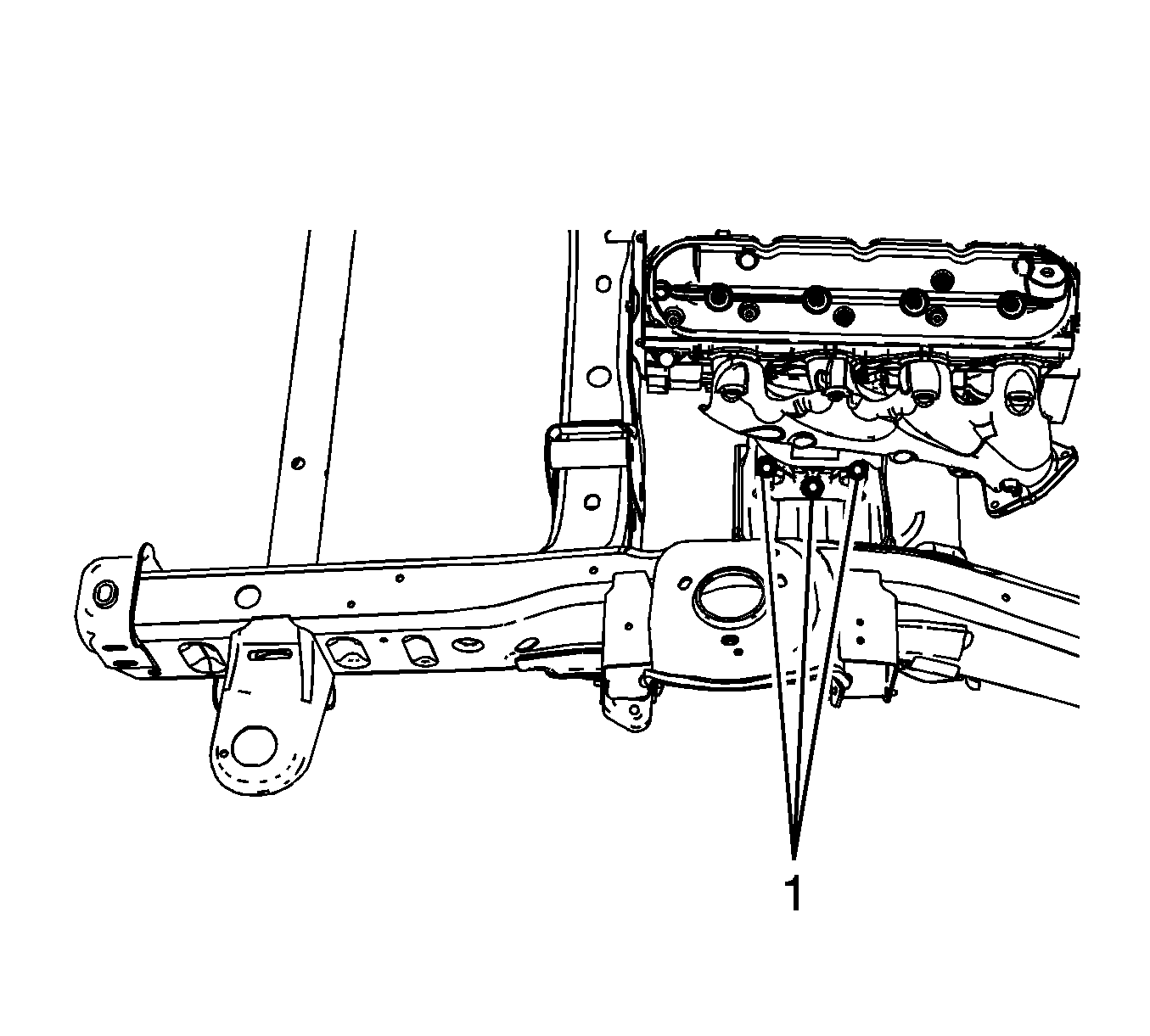
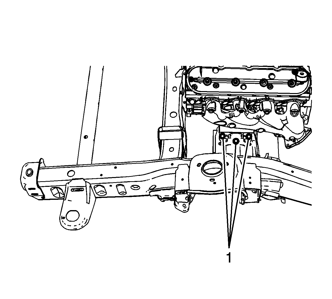
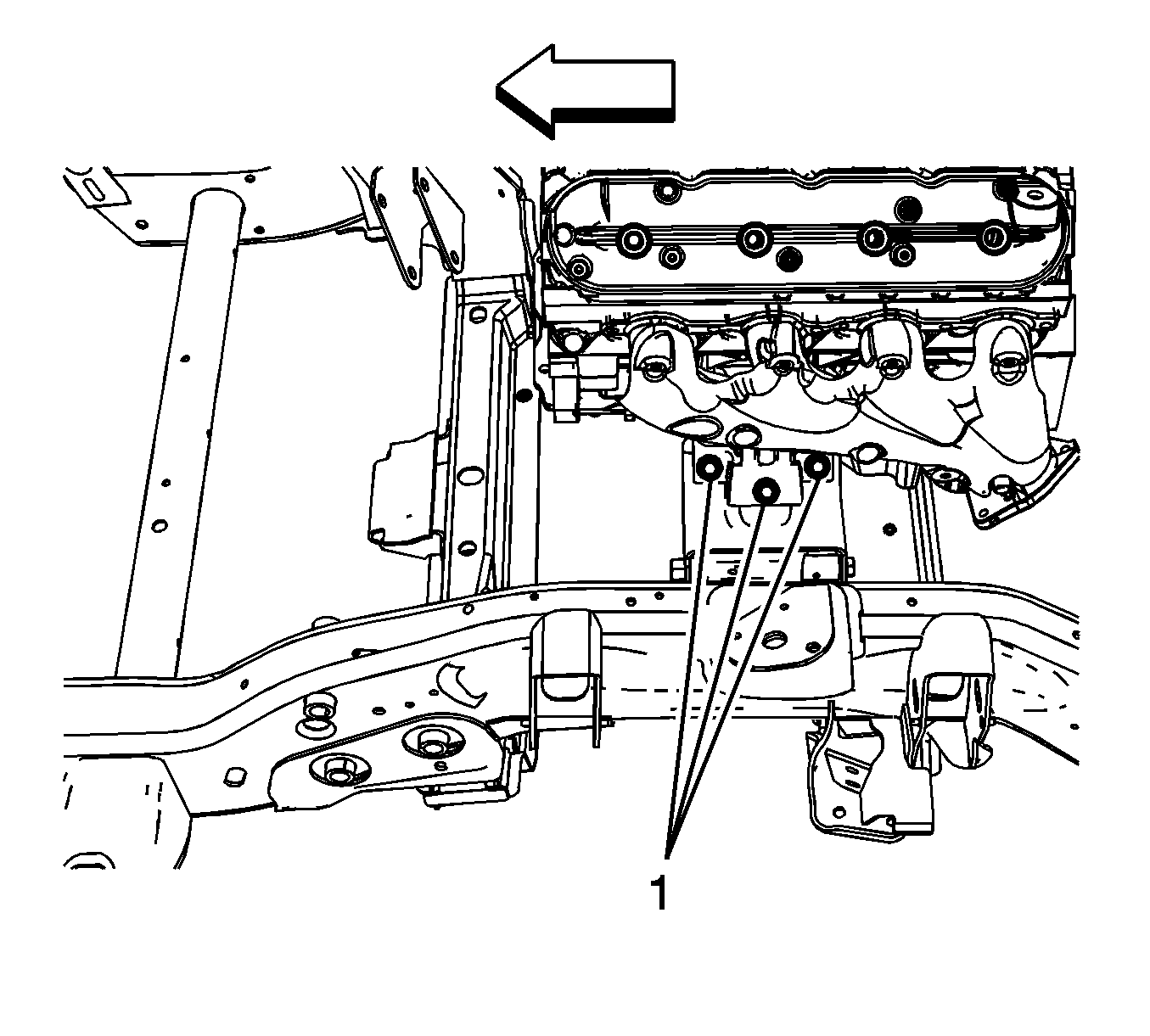
Tighten
Tighten the drain plug to 25 N·m (18 lb ft).

Installation Procedure
- Install the J 41798 Engine Lift Bracket to the engine.
- Tighten the M8 engine lift bracket bolts to 25 N·m (18 lb ft).
- Tighten the M10 engine lift bracket bolts to 50 N·m (37 lb ft).
- Position and install the engine hoist to the J 41798 Engine Lift Bracket .
- Remove the engine from the engine stand.
- Remove the J 21366 Converter Holding Strap from the transmission.
- Install the engine to the vehicle.
- Align and install the engine to the transmission. Raise or lower the transmission as required using the floor jack.
- Once aligned and mated together completely lower and remove the engine hoist.
- For 2500 series vehicles with a 5.3L, 6.0L, or 6.2L engine, install the left and right engine mount to engine mount bracket bolts (1) and tighten to 65 N·m (48 lb ft).
- For 1500 series vehicles with a 5.3L, 6.0L, or 6.2L engine, install the left and right engine mount to frame bolts (1) and tighten to 65 N·m (48 lb ft).
- For 1500 series vehicles with a 4.8L engine, install the left and right engine mount to frame bolts (1) tighten to 65 N·m (48 lb ft).
- Remove the floor jack from under the transmission.
- Raise the vehicle.
- If equipped with the 6L80-E automatic transmission, install the transmission bolts/studs and tighten to 50 N·m (37 lb ft).
- If equipped with the 4L80-E automatic transmission, install the transmission bolts/studs and tighten to 50 N·m (37 lb ft).
- If equipped with the 4L60-E/4L70-E automatic transmission, install the transmission bolts/studs and tighten to 50 N·m (37 lb ft).
- Position the transfer case vent hose bracket and hose and install the bracket to the stud, if equipped.
- For the 4L60-E/4L70-E/6L80-E automatic transmission, install the transfer case vent hose bracket (2) nut to the stud, if equipped and tighten to 20 N·m (15 lb ft).
- For the 4L80-E automatic transmission, install the transfer case vent hose bracket (1) nut to the stud, if equipped and tighten to 20 N·m (15 lb ft).
- Position the fuel/EVAP pipe bracket and install the bracket to the stud. (typical installation shown).
- Install the fuel/EVAP pipe bracket nut to the transmission stud and tighten to 20 N·m (15 lb ft).
- Align the torque converter bolt holes to the flywheel bolt holes.
- Install the flywheel to torque converter bolts.
- For the 4L60-E/4L70-E/6L80-E automatic transmission, tighten the bolts to 63 N·m (47 lb ft).
- For the 4L80-E automatic transmission, tighten the bolts to 60 N·m (44 lb ft).
- Install the catalytic converter. Refer to Catalytic Converter Replacement or Three-Way Catalytic Converter Replacement.
- Lower the vehicle.
- Remove the J 41798 Engine Lift Bracket from the cylinder heads.
- Install the ignition coil(s) and spark plug wire(s), as required. Refer to Ignition Coil Replacement.
- Install the transmission oil level indicator tube.
- Install the transmission oil level indicator tube nut (1) and tighten to 18 N·m (13 lb ft).
- Position the generator bracket (with power steering pump) to the engine.
- Install the generator bracket bolts and tighten to 50 N·m (37 lb ft).
- Install the rear power steering pump-to-engine block bolt (1500 series shown, 2500 series similar) and tighten to 50 N·m (37 lb ft).
- Raise the vehicle.
- Connect the coolant heater cord to the coolant heater, if equipped.
- Connect the engine harness electrical connector (1) to the CKP sensor.
- Connect the engine harness electrical connector (2) to the knock sensor.
- Connect the engine harness electrical connector (4) to the oil level sensor.
- Install the engine harness clip (3) to the transmission oil cooler line bracket.
- Install the starter motor. Refer to Starter Motor Replacement.
- Connect the engine harness electrical connector (1) to the A/C refrigerant pressure sensor.
- Slide the channel pin (3) into the oil pan tab.
- Install the battery cable channel bolt (2) and tighten to 12 N·m (106 lb in).
- Connect the engine harness electrical connector (1) to the CMP sensor wire harness.
- Position the transmission oil cooler line clip to the oil pan and install the bolt, if equipped and tighten to 9 N·m (80 lb in).
- Connect the engine harness electrical connector (4) to the knock sensor.
- Position the engine harness grounds (3) to the engine block.
- Install the engine harness ground stud (2) to the engine block and tighten to 16 N·m (12 lb ft).
- Install the engine harness clip (1) to the ground stud.
- Lower the vehicle.
- Position the negative battery cable terminal (2) and the engine harness ground (3) to the right cylinder head.
- Install the negative battery cable stud (1) to the right cylinder head and tighten to 25 N·m (18 lb ft).
- Position the engine ground strap to the cylinder head and cowl.
- Install the engine ground strap bolt to the rear of the left cylinder head and cowl and tighten to 16 N·m (12 lb ft).
- Connect the engine harness electrical connector (1) to the oil pressure sensor.
- Connect the engine harness electrical connector (2) to the lifter oil manifold.
- Install the heater hoses. Refer to Heater Inlet Hose Replacement and Heater Outlet Hose Replacement.
- Install the radiator outlet hose to the water pump.
- Position the radiator outlet hose clamp at the water pump.
- Install the radiator inlet hose to the water pump.
- Position the radiator inlet hose clamp (3) at the water pump.
- Position and install the radiator vent inlet hose (2) to the air bleed pipe.
- Position the radiator vent inlet hose clamp (1) at the air bleed pipe.
- Install the radiator vent inlet hose (2) to the radiator inlet hose clip (3).
- Position the generator battery jumper to the engine.
- Install the intake manifold. Refer to Intake Manifold Replacement.
- For 2500 series vehicles, install the oil pan skid plate and bolts, if equipped and tighten to 28 N·m (21 lb ft).
- For 1500 series vehicles, install the oil pan skid plate and bolts, if equipped and tighten to 28 N·m (21 lb ft).
- Install the engine shield and bolts and tighten to 20 N·m (15 lb ft).
- Lower the vehicle.
- Install the front end upper tie bar. Refer to Front End Upper Tie Bar Replacement.
- Install the hood latch. Refer to Hood Primary and Secondary Latch Replacement.
- With the aid of the assistant raise the hood slightly until the hood hinge bolts can be removed from the service position notch (1).
- With the aid of an assistant lower the hood and install the hood hinge bolts (3) to the hood hinges and tighten to 25 N·m (18 lb ft).
- Install the hood strut rod (1) to the hood strut bracket stud.
- Install the air inlet grille end caps (2), push down the end cap in order to engage the retainers. (left side shown, right side similar).
- Install the ground strap to the hood stud.
- Install the ground strap nut at the hood stud.
- Prelube the engine. Refer to Engine Prelubing.
- Perform the CKP system variation learn procedure. Refer to Crankshaft Position System Variation Learn.
- Close the hood.

Caution: Refer to Fastener Caution in the Preface section.

Note: Start with the middle bolt then either side bolt.

Note: Start with the middle bolt then either side bolt.

Note: Start with the middle bolt then either side bolt.


Note: There is a positive stop which limits the hood from being opened too far.


Tighten
Tighten the nut to 9 N·m (80 lb in).
Note: After an overhaul the engine should be tested. Use the following procedure after the engine is installed in the vehicle.
| • | Disable the ignition system. |
| • | Crank the engine several times. Listen for any unusual noises or evidence that parts are binding. |
| • | Enable the ignition system. |
| • | Start the engine and listen for unusual noises. |
| • | Check the vehicle oil pressure gauge or light and confirm that the engine has acceptable oil pressure. |
| • | Run the engine speed at about 1,000 RPM until the engine has reached normal operating temperature. |
| • | Listen for sticking lifters or other unusual noises. |
| • | Inspect for fuel, oil and/or coolant leaks while the engine is running. |
| • | Perform a final inspection for the proper oil and coolant levels. |
