GM Service Manual Online
For 1990-2009 cars only

Tools Required

DT-47825 Control Solenoid Test Kit

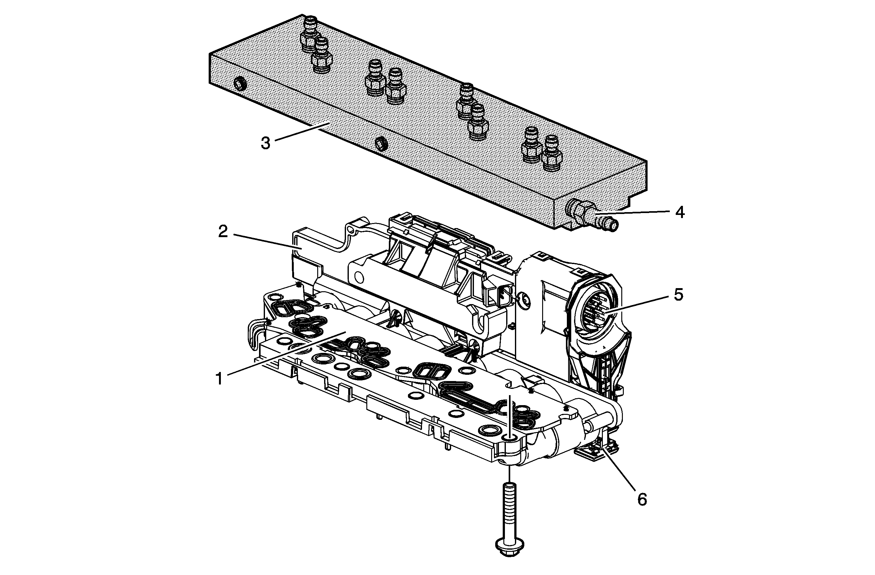
Control Solenoid (w/Body and TCM) Valve Assembly with Control Solenoid Test Plate


Object Number: 1690098  Size: MF
(1)Filter Plate Assembly
(2)Control Solenoid Valve Assembly
(3)DT-47825 Control Solenoid Test Plate
(4)Air Connection Port
(5)Transmission 16-Way Pass-Through Connector
(6)Electrical Connector Slide Lock

The purpose of this procedure is to test the functionality of the control solenoid (w/body and TCM) valve assembly solenoids for a gross stuck open or stuck closed condition, or a faulty transmission fluid pressure (TFP) switch. DT-47825 is bolted to the control solenoid (w/body and TCM) valve assembly on the valve body mounting surface. Pressurized air is passed into the aluminum test block, through the control solenoid (w/body and TCM) valve assembly solenoid passage and back to the outlet port on the test block. A scan tool is used to command the solenoids ON and OFF. While observing the airflow, one can determine the valve functionality. The recommended shop air pressure for this test is regulated to 90-100 psi.
Preliminary Procedures

  1. Raise and support the vehicle. Refer to Lifting and Jacking the Vehicle.
  2. Remove the transmission fluid pan and filter. Refer to Automatic Transmission Fluid, Fluid Pan and/or Filter Replacement.
  3. Remove the transmission electrical connector. Refer to Automatic Transmission Electrical Connector Passage Sleeve Replacement.
  4. Remove the control solenoid (w/body and TCM) valve assembly from the transmission. Refer to Control Valve Lower Body and Upper Body Replacement.
  5. Perform the Control Solenoid Valve and Transmission Control Module Assembly Inspection procedure.

Solenoid Testing Procedure


Object Number: 1690103  Size: MF
(1)Regulated Air Supply
(2)Test Ports
(3)Scan Tool
(4)Test Pressure Gage
(5)Electrical Connector Sleeve

Notice: The automatic transmission (A/T) electrical connector passage sleeve allows the test tool harness to be correctly orientated for electrical operation of the transmission control module (TCM). Do not connect the test harness to the TCM without using the A/T Electrical Connector Passage Sleeve. Failure to use the sleeve could allow the test harness to be incorrectly positioned which will result in permanent TCM damage.

Notice: To avoid solenoid overheating and possible internal damage, do not continuously operate the solenoid for more than 2 minutes at a time. Drain the TCM of excess transmission fluid before attaching to test block and use caution when attaching air to test block air inlet.

Important: With the ignition ON and the engine OFF, the transmission control module (TCM) will normally cycle some of the transmission solenoids On and Off to facilitate keeping the ports and solenoids clean and free of debris. This dither function is a normal activity and will cause the valves to cycle open and closed quickly when the TCM is powered up. This may cause some air to exit the ports where the PSI gauge is not connected as those solenoids cycle on and off.

  1. Align and install the electrical connector sleeve to the control solenoid (w/body and TCM) valve assembly and secure with the connector slide lock.
  2. If necessary, clean each side of the filter plate assembly and install the filter plate assembly back on the control solenoid (w/body and TCM) valve assembly. Clean the mounting surface of the DT-47825 .
  3. Bolt the DT-47825 to the control solenoid (w/body and TCM) valve assembly mounting surface. Use the bolts and washers supplied with the tool to attach the test block. Tighten the bolts to 5 N·m (44 lb in).
  4. Connect the test harness supplied with the DT-47825 to the vehicle harness and to the control solenoid (w/body and TCM) valve assembly. Engage the connector locks.
  5. Turn the ignition ON.
  6. Cover the DT-47825 test block ports with a shop towel. Transmission fluid may exit these ports when the solenoids are commanded ON.
  7. Connect regulated shop air to the DT-47825 air inlet. Do not exceed the recommended air pressure of 620.5-689.4 Kpa (90-100 psi).
  8. With a scan tool, in the Hybrid Control Module Special Functions menu, command the Aux. Trans. Pump Speed to 75 percent for 5 seconds. Failure to command the Aux. Trans. Pump Speed to 75 percent for 5 seconds will prevent the Shift Solenoid 1 from functioning correctly during testing. Do not turn off the ignition for the remainder of these tests.
  9. With the ignition ON and the scan tool communicating with the vehicle, command the solenoid in question On and Off. Observe the airflow at the appropriate test port for a change as you command the solenoid. Refer to Control Solenoid (w/Body and TCM) Valve Assembly Solenoid Performance Test Plate to Component Identification for correct solenoid function and test plate port connections for the solenoid being tested.
  10. The solenoid should allow air pressure to flow or prevent air pressure flow depending on the solenoid state. The test results are read on the pressure gage.
  11. Command the solenoid valve On and Off several times to determine the condition of the solenoid in question. Release the test air pressure from the pressure the gage between solenoid tests.

Control Solenoid (w/Body and TCM) Valve Assembly Solenoid Performance Test Block to Component Identification

Component

Port On Test Block

Ignition ON, Engine OFF Normal State

Commanded State

Line PC Solenoid

A

No PSI flow to gage

Increase/Decrease Approximately 68-103 Kpa (10-15 psi) per command

PC Solenoid 2

D, G, H

No PSI flow

On - Full PSI flow

Off - No PSI flow

PC Solenoid 3

C, H

No PSI flow

On - Full PSI flow

Off - No PSI flow

PC Solenoid 4

D, E, H

No PSI flow

On - Full PSI flow

Off - No PSI flow

PC Solenoid 5

F

No PSI flow to gage

On - Full PSI flow to gage

Off - No PSI flow to gage

PC Solenoid 6 - Not Used, cannot be commanded with the scan tool

B

No PSI flow

On - Full PSI flow

Off - No PSI flow

Shift Solenoid 1

H

No PSI flow

On - Full PSI flow

Off - No PSI flow

Shift Solenoid 2

D

No PSI flow

On - Full PSI flow

Off - No PSI flow

Transmission Fluid Pressure (TFP) Switch Test Procedure

Control Solenoid (W/Body and TCM) Valve Assembly


Object Number: 1628036  Size: SF
(1)Pressure Control (PC) Solenoid 2
(2)Pressure Control (PC) Solenoid 4
(3)Shift Solenoid (SS) 2
(4)16 Pin Connector
(5)Line Pressure Control (PC) Solenoid
(6)Transmission Fluid Pressure (TFP) Switch 5
(7)Pressure Control (PC) Solenoid 6 - Not Used
(8)Pressure Control (PC) Solenoid 3
(9)Transmission Fluid Pressure (TFP) Switch 3
(10)Transmission Fluid Pressure (TFP) Switch 1
(11)Transmission Fluid Pressure (TFP) Switch 4
(12)Pressure Control (PC) Solenoid 5
(13)Shift Solenoid (SS) 1
  1. Remove the DT-47825 from the control solenoid (w/body and TCM) valve assembly.
  2. With the ignition ON and the scan tool communicating with the vehicle, using a soft blunt object, depress each transmission fluid pressure (TFP) switch port. The corresponding TFP Switch parameter on the scan tool display should display HI when depressed and Low when released.
  3. If the control solenoid (w/body and TCM) valve assembly fails any of the above tests, replace the control solenoid (w/body and TCM) valve assembly.
    If the control solenoid (w/body and TCM) valve assembly passes the above tests, the concern is internal to the transmission.

Repair Instructions

Perform the Diagnostic Repair Verification after completing the diagnostic procedure.

Control Module References for control solenoid (w/body and TCM) valve assembly replacement, setup, and programming.