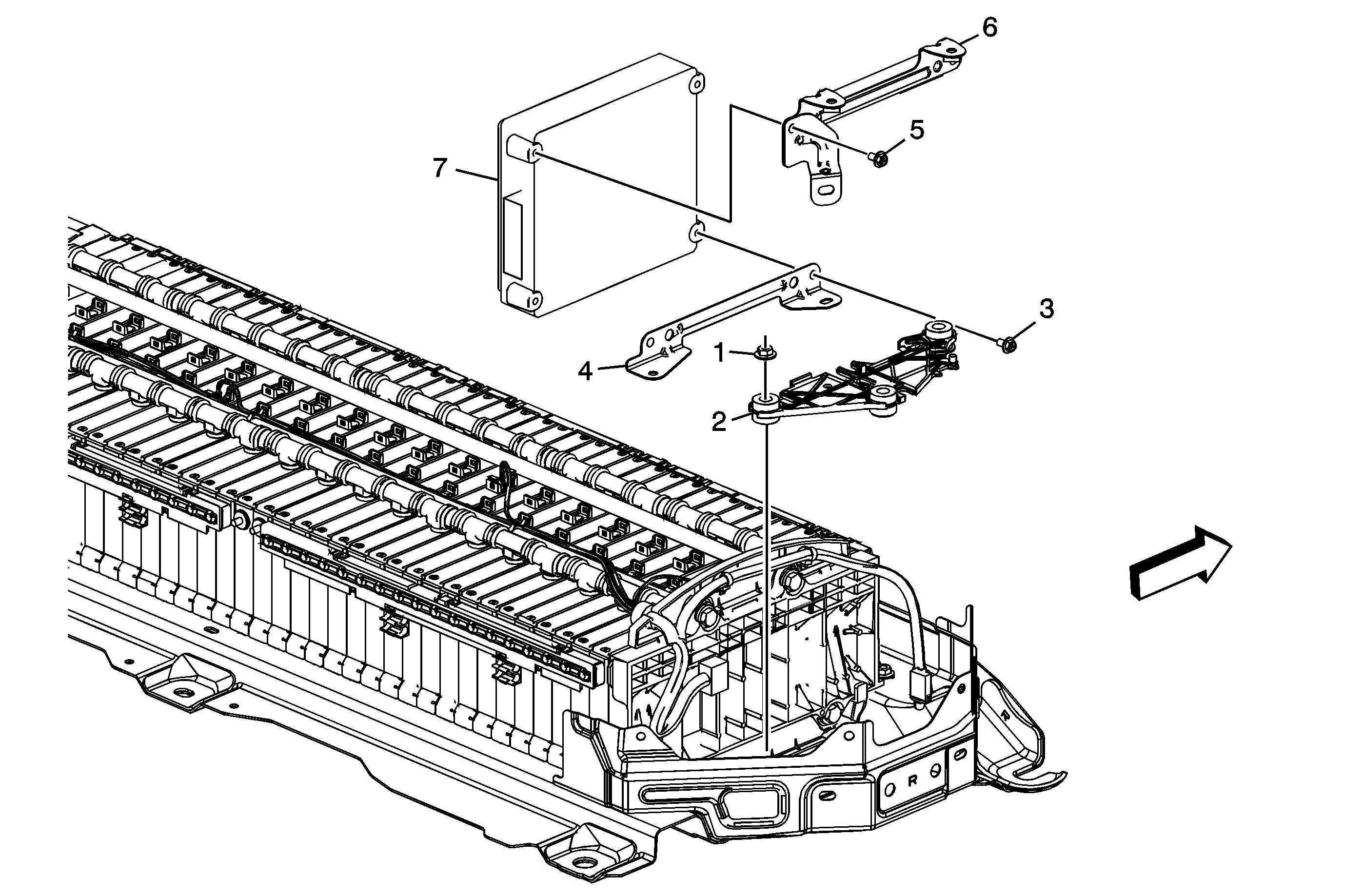
Callout | Component Name | ||||||
|---|---|---|---|---|---|---|---|
|
Danger: Always perform the High Voltage Disabling procedure prior to servicing any High Voltage component or connection. Personal Protection Equipment (PPE) and proper procedures must be followed. The High Voltage Disabling procedure will perform the following tasks:
Preliminary Procedures
| |||||||
1 | Drive Motor Battery Positive High Voltage Contactor Relay Nut | ||||||
2 | Drive Motor Battery Power Inverter Current Limit Relay Connector | ||||||
3 | Drive Motor Generator Battery Positive Relay Insulator Nut (Qty: 3) Caution: Refer to Fastener Caution in the Preface section. Tighten | ||||||
4 | Drive Motor Generator Battery Positive Relay Insulator Assembly | ||||||
5 | Drive Motor Generator Battery Positive Relay Insulator Assembly | ||||||
6 | Drive Motor Battery Control Module Bracket Bolt (Qty: 2) Tighten | ||||||
7 | Drive Motor Battery Control Module Lower Bracket | ||||||
8 | Drive Motor Battery Control Module Upper Bracket Bolt (Qty: 2) Tighten | ||||||
9 | Drive Motor Battery Control Module Upper Bracket | ||||||
10 | Drive Motor Generator Battery Control Module Assembly Procedure
| ||||||
