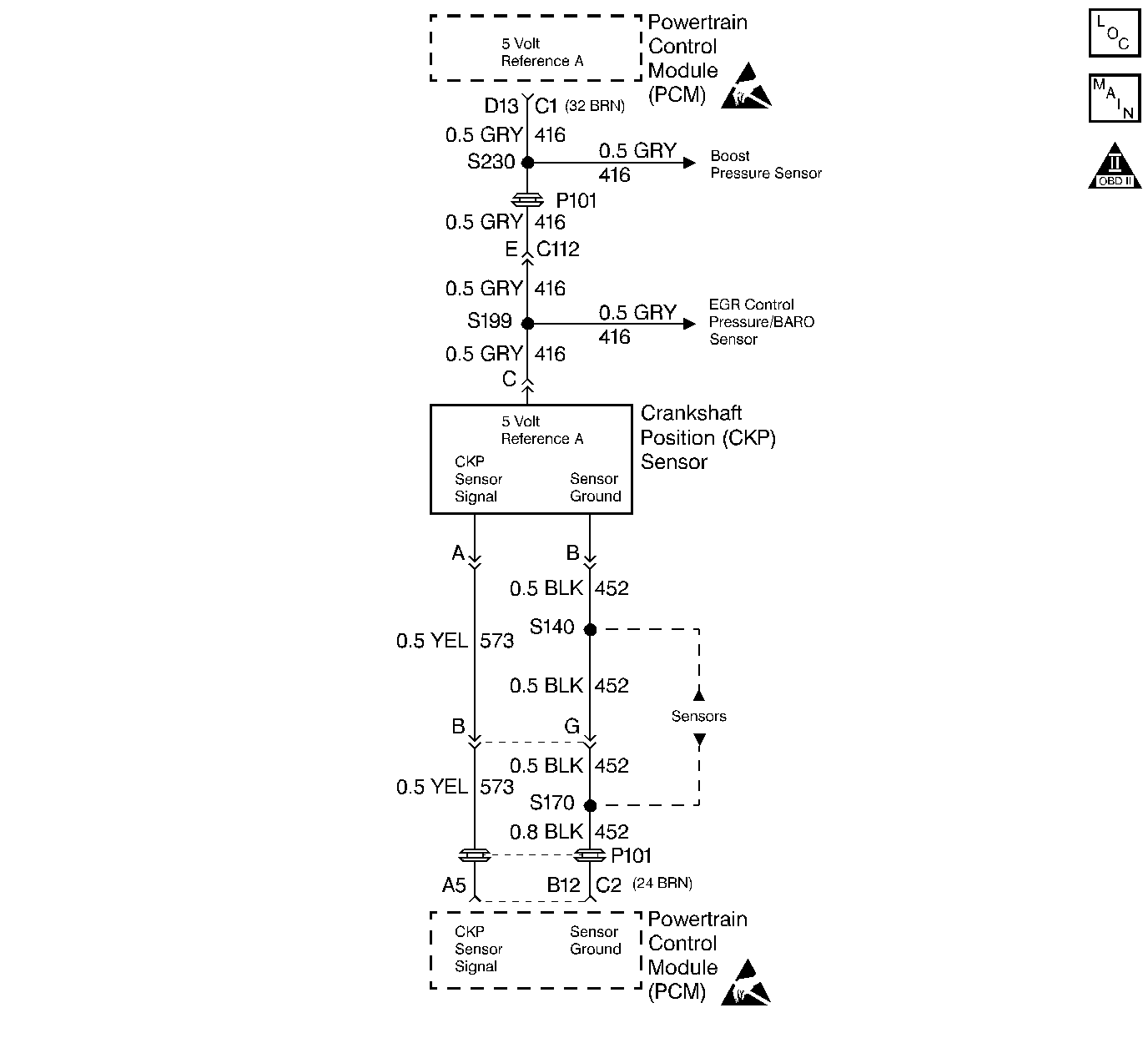
Circuit Description
The PCM provides a 5 volt supply for use in powering up sensors. This test monitors the voltage present at terminals BRD13 (shared by Boost, EGR Control Pressure/BARO and Crankshaft Position sensors) and BRD14 (Optical/Fuel temperature sensor (Cam/HI.Res). This is a type D DTC.
Conditions for Setting the DTC
5 volt reference is less than 1 volt.
Action Taken When the DTC Sets
| • | Backup fuel |
| • | No EGR. |
| • | No turbo boost. |
Conditions for Clearing the MIL/DTC
| • | A History DTC will clear when forty consecutive warm-up cycles that the diagnostic does not fail (coolant temperature has risen 5°C (40°F) from start up coolant temperature and engine coolant temperature exceeds 71°C (160°F) that same ignition cycle. |
| • | Use of a Scan tool |
Diagnostic Aids
During the time the failure is present, the setting of additional DTCs that share a 5 volt reference may also set.
Test Description
Number(s) below refer to the step number(s) on the Diagnostic Table.
-
Checks to confirm that a DTC is still present.
-
Checks to determine if there is a 5 volt reference from the PCM.
-
Checks to determine if there is a short-to-ground in the reference circuit or a short-to-ground in the PCM.
-
This step determines if the short is being caused by one of the sensors on the engine or the short is in the wiring harness.
Step | Action | Value(s) | Yes | No |
|---|---|---|---|---|
1 |
Important: Before clearing DTCs use the scan tool Capture Info to record freeze frame and failure records for reference, as data will be lost when Clear Info function is used. Was the Powertrain On-Board Diagnostic (OBD) System Check performed? | -- | ||
Does the DTC reset? | -- | |||
Is the voltage less than the specified value? | 4.0 V | |||
Is the test light ON? | -- | |||
5 | The DTC is intermittent. If no additional DTCs are stored, refer to Diagnostic Aids. If additional DTCs were stored refer to those table(s). Are any additional DTCs stored? | -- | Go to the Applicable DTC table | Go to Diagnostic Aids |
6 | Replace the Boost sensor. Refer to Boost Sensor (Diesel) . Is the action complete? | -- | -- | |
With the test light still probing the Boost sensor 5 volt reference circuit at the PCM, disconnect each sensor, one at a time, that shares the 5 volt reference with the Boost sensor. Does the test light turn OFF when one of the sensors are disconnected? | -- | |||
8 | Replace the sensor that caused the test light to turn OFF. Is the action complete? | -- | -- | |
9 | Repair the short to ground in 5 volt reference circuit. Is the action complete? | -- | -- | |
10 | Replace the PCM. Important: The new PCM must be programmed. Refer to Powertrain Control Module Replacement/Programming . Is the action complete? | -- | -- | |
11 |
Does the Scan Tool indicate that the diagnostic Passed? | -- | ||
12 | Using the Scan Tool, select Capture Info, Review Info. Are any DTCs displayed that have not been diagnosed? | -- | Go to the Applicable DTC table | System OK |
