The fuel metering system consists of the following parts:
| • | The fuel supply components, fuel tank, pump, pipes |
| • | The fuel pump electrical circuit |
| • | The fuel pressure regulator |
| • | The idle air control (IAC) valve |
| • | The throttle position (TP) sensor |
System Overview
The fuel tank stores the fuel supply. An electric fuel pump attaches
to the fuel sender assembly inside the fuel tank. The fuel pump sends fuel
through the fuel feed pipe and an in-line fuel filter to the fuel rail
assembly. The pump provides fuel at a pressure more than is needed by the
injectors. The fuel pressure regulator, part of the fuel rail assembly,
keeps fuel available to the injectors at a regulated pressure. A separate
fuel return pipe returns the unused fuel to the fuel tank.
Fuel Pump Electrical Circuit
When the ignition switch is in the ON position, before engaging the
starter, the powertrain control module (PCM) energizes the fuel pump relay
for 2 seconds, causing the fuel pump to pressurize the fuel system.
If the PCM does not receive ignition reference pulses, engine cranking
or running, within 2 seconds, the PCM shuts OFF the fuel pump relay,
causing the fuel pump to stop.
Fuel Rail Assembly
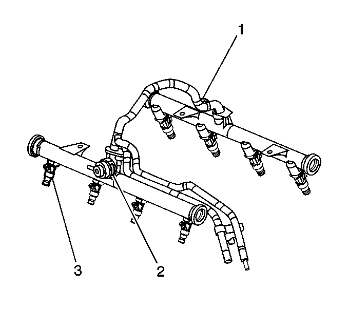
The fuel rail assembly
attaches to the engine intake manifold. The fuel rail assembly performs the
following functions:
| • | Positions the injectors (3) in the intake manifold |
| • | Distributes fuel evenly to the injectors |
| • | Integrates the fuel pressure regulator (2) with the fuel
metering system |
Fuel Injectors
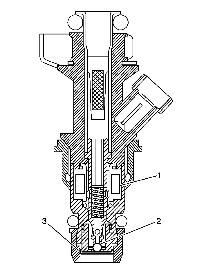
The Multec 2 fuel injector assembly is a solenoid
operated device, controlled by the PCM, that meters pressurized fuel to a
single engine cylinder. The PCM energizes the high-impedance (12.2 ohms)
injector solenoid (1) to open a normally closed ball valve (2). This allows
fuel to flow into the top of the injector, past the ball valve, and through
a director plate (3) at the injector outlet. The director plate has four
machined holes that control the fuel flow, generating a spray of finely
atomized fuel at the injector tip. Fuel from the injector tip
is directed at the intake valve, causing it to become further atomized and
vaporized before entering the combustion chamber. An injector stuck partly
open can cause a loss of pressure after engine shutdown. Consequently, long
cranking times would be noticed on some engines.
Fuel Pressure Regulator Assembly
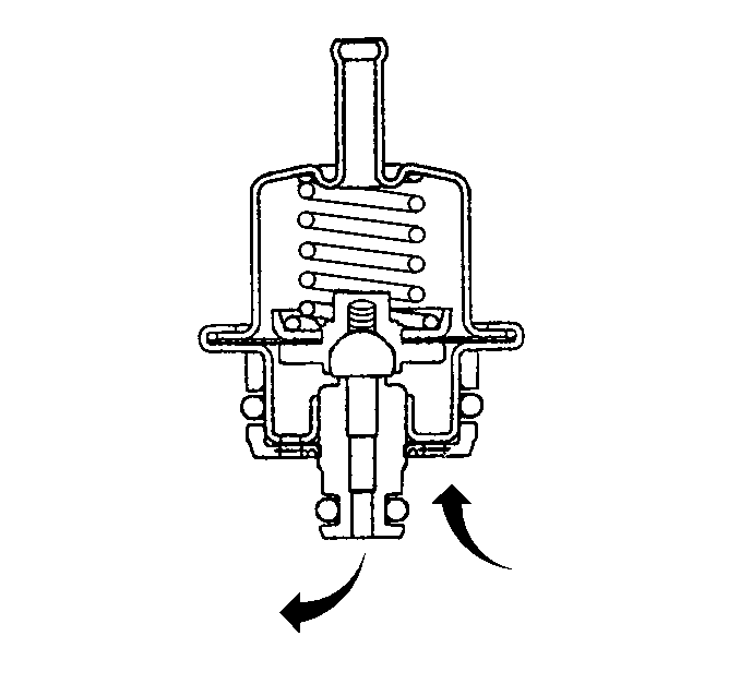
The fuel pressure regulator
is a diaphragm operated relief valve with fuel pump pressure on one side and
regulator spring pressure and intake manifold vacuum on the other side.
The fuel pressure regulator maintains a constant pressure differential
across the injectors at all times. The pressure regulator compensates for
engine load by increasing fuel pressure as the engine vacuum drops. With
the ignition ON and the engine OFF, system fuel pressure at the pressure
test connection should be 379-427 kPa (55-62 psi).
If the pressure is too low, reduced performance may result. If the pressure
is too high, excessive odor and a diagnostic trouble code (DTC) P0132,
P0152, P0172 or P0175 may result. Refer to
Fuel System Diagnosis
for information on diagnosing fuel pressure
conditions.
Accelerator Controls
The accelerator control system is cable operated. There are no linkage
adjustments, therefore use the specific cable for each application.
Throttle Body Assembly
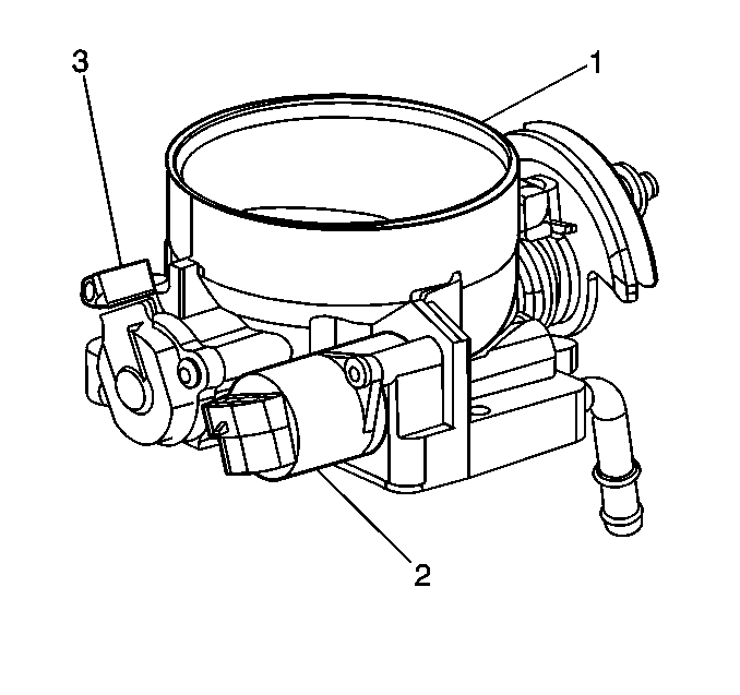
The throttle body assembly (1)
attaches to the intake manifold. The throttle body controls air flow into
the engine, thereby controlling engine output. The vehicle operator opens
the throttle valve within the throttle body through the accelerator controls.
During engine idle, the throttle valves are almost closed. A fixed air
bypass orifice and the idle air control (IAC) valve (2) handle the
air flow control. Engine coolant flows through the coolant cavity on the
bottom of the throttle body in order to prevent throttle valve icing during
cool weather operation. The throttle body also provides the location for
mounting the throttle position (TP) sensor (3).
Idle Air Control (IAC) Valve
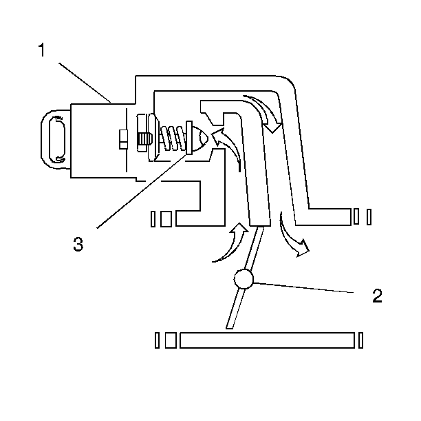
The purpose of the IAC valve is to control engine idle speed, while
preventing stalls due to changes in engine load. The IAC valve, mounted in
the throttle body, controls a portion of the bypass air. An orifice located
between the throttle valves also supplies a constant amount of bypass
air. By moving a conical valve known as a pintle (3) in toward the
seat, to decrease air flow, or out away from the seat, to increase air
flow, a controlled amount of air can be bypassed. If engine speed is too
low, more air is bypassed in order to increase RPM. If engine speed is too
high, less air is bypassed in order to decrease RPM. The PCM moves the IAC
valve in small steps, called counts. These can be measured and displayed
with a scan tool, which plugs into the data link connector (DLC). The
PCM calculates the proper position of the IAC valve during idle based upon
the battery voltage, the coolant temperature, the engine load, and the engine
RPM. If the RPM drops below specification and the throttle valve is closed, the
PCM senses a near stall condition and calculates a new valve position
in order to prevent stalling.
| • | Engine idle speed is a function of total air flow into the engine.
Idle speed is based on IAC valve pintle position, crankcase ventilation valve
flow, throttle valve opening, bypass orifice air flow, and calibrated vacuum
loss through accessories. |
| • | Controlled idle speed is programmed into the PCM, which determines
the correct IAC valve pintle position to maintain the desired idle speed for
all engine operating conditions and loads. |
| • | The minimum idle air rate is set at the factory with a stop screw.
This setting allows enough air flow by the throttle valves to cause the IAC
valve pintle to be positioned a calibrated number of steps, counts, from
the seat, during controlled idle operation. |
| • | If the IAC valve is disconnected and reconnected with the engine
running, the idle speed may be wrong. If this occurs, reset the IAC valve
by depressing the accelerator pedal slightly, starting and running the
engine for 5 seconds, and then turning the ignition OFF for 10 seconds. |
Throttle Position (TP) Sensor
The TP sensor attaches to the side of the throttle body opposite the
throttle lever. The TP sensor measures the throttle valve angle and relays
that information to the PCM. The PCM requires knowledge of the throttle angle
in order to generate the required injector control signals, pulses.


