Ignition System Overview
The electronic ignition system controls fuel combustion by providing
a spark to ignite the compressed air/fuel mixture at the correct time. The
powertrain control module (PCM) controls the spark advance of the ignition
system in order to provide optimum engine performance, fuel economy, and
control of exhaust emissions. The electronic ignition system has
the following advantages over a mechanical distributor ignition system:
| • | Remote mounting capability |
| • | No mechanical load on the engine |
| • | More coil cool down time between firing events |
| • | Elimination of mechanical timing adjustments |
| • | Increased available ignition coil saturation time |
The electronic ignition system does not use the conventional
distributor and coil. The ignition system consists of the following components
or circuits:
| • | The 8 ignition coils or modules |
| • | The 8 ignition control (IC) circuits |
| • | The camshaft position (CMP) sensor |
| • | The 1X camshaft reluctor wheel |
| • | The crankshaft position (CKP) sensor |
| • | The 24X crankshaft reluctor wheel |
| • | The related connecting wires |
| • | The powertrain control module (PCM) |
Crankshaft Position Sensor and Reluctor Wheel

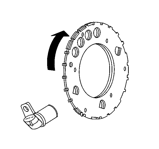
The crankshaft position
(CKP) sensor is located in the lower right rear of the engine, behind the
starter. The CKP sensor is a dual magneto resistive type sensor.
This sensor is not speed dependent. The dual micro switches monitor
both notches of the reluctor wheel for greater accuracy. The CKP
sensor works in conjunction with a 24X reluctor wheel. The reluctor
wheel is mounted on the rear of the crankshaft. The 24X reluctor
wheel uses 2 different width notches that are 15 degrees apart. This
pulse width encoded pattern allows cylinder position identification
within 90 degrees of crankshaft rotation. In some cases, cylinder
identification can be located in 45 degrees of crankshaft rotation.
This reluctor wheel also has dual track notches that are 180 degrees
out of phase. The dual track design allows for quicker starts and
accuracy.
The PCM also receives a 4X signal from the crankshaft position sensor.
The PCM utilizes the 4X signal for the following:
The CKP signal must be available for the engine to start. The CMP signal
is not needed to start and operate the engine. The PCM can determine when
a particular cylinder is on either a firing or exhaust stroke by
the 24X signal. The CMP sensor is to determine what stroke the engine
is on. The system attempts to synchronize and look for an increase
in the mass air flow (MAF) signal. An increase in the MAF signal
indicates the engine has started. If the PCM does not detect an
increase in the MAF signal, a re-synchronize occurs to the opposite
cam position. A slightly longer cranking time may be a symptom of
this condition.
Camshaft Position Sensor

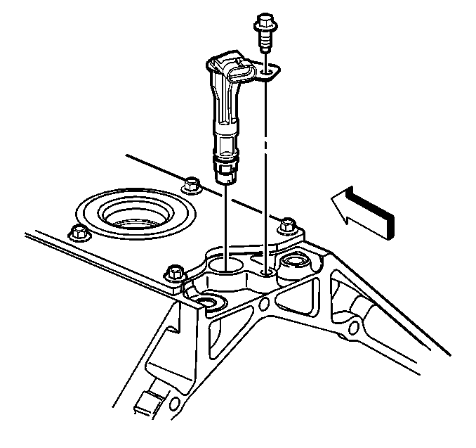
The camshaft position
(CMP) sensor is mounted through the top of the engine block at the rear of
the valley cover. The CMP sensor works in conjunction with a 1X
reluctor wheel. The reluctor wheel is located at the rear of the
camshaft. The CMP sensor is used to determine whether a cylinder
is on the firing or the exhaust stroke. As the camshaft rotates,
the reluctor wheel interrupts a magnetic field produced by a magnet
within the sensor. The CMP sensor internal circuitry detects this
and produces a signal which is used by the PCM. The PCM uses this
signal in combination with the CKP 24X signal in order to determine
crankshaft position and stroke.
The CKP signal must be available for the engine to start. The CMP signal
is not needed to start and operate the engine. The PCM can determine when
a particular cylinder is on either a firing or exhaust stroke by
the 24X signal. The CMP sensor is used to determine what stroke
the engine is on. The system will attempt to synchronize and look
for an increase in the MAF signal. An increase in the MAF signal
indicates the engine has started. If the PCM does not detect an
increase in the MAF signal, a re-synchronize occurs to the opposite
cam position. A slightly longer cranking time may be a symptom of
this condition.
Ignition Coils/Module

The ignition system on
this vehicle features a multiple coil configuration and is known as coil
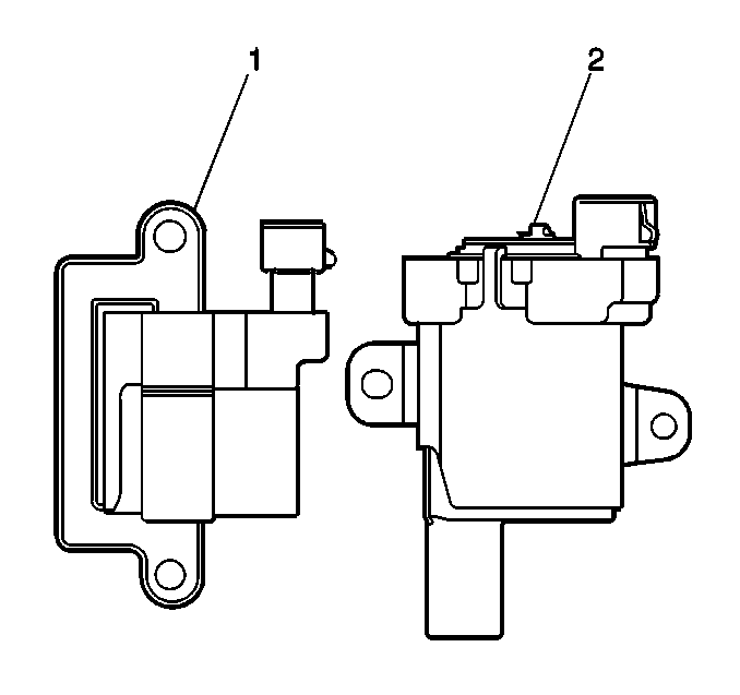
near plug. There are two styles of ignition coil assemblies (1,2).
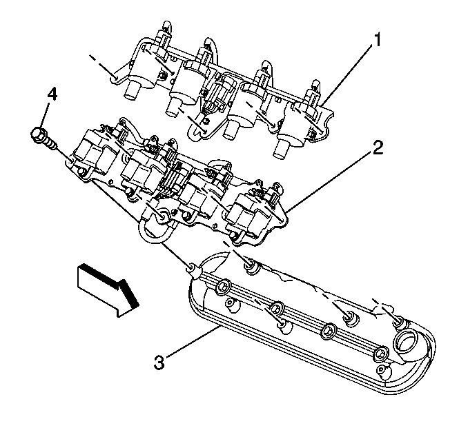
The engine could have either style. The ignition coil mounting bracket
is attached to the rocker cover. The secondary ignition wires are short
compared to a distributor ignition system wire.

The 8 ignition coils or modules are individually mounted above
each cylinder on the rocker covers (3). The coils/modules are fired
sequentially. There is an ignition control (IC) circuit for each
ignition coil or module. The 8 ignition control circuits are connected
to the PCM. The PCM triggers each ignition coil/module individually
and makes all timing decisions. The ignition coil or modules are supplied
with the following circuits:
| • | The ignition feed circuit |
| • | The ignition control circuit |
| • | The reference low circuit |
The ignition feed circuits are fused separately for each bank of the
engine. The 2 fuses also supply the power for the injectors for that bank
of the engine. Each coil or module is serviced separately.
This system puts out very high ignition energy for plug firing. Less
energy is lost to ignition wire resistance because the ignition wires are
shorter. Since the firing is sequential, each coil has 7 events to saturate
as opposed to the 3 in a waste spark arrangement. Futhermore, no
energy is lost to the resistance of a waste spark system.
Circuits Affecting Ignition Control
To properly control ignition timing, the PCM relies on the following
information:
| • | The engine load, manifold pressure or vacuum |
| • | The atmospheric, barometric, pressure |
| • | The intake air temperature |
| • | The crankshaft position |
The ignition control (IC) system consists of the following components:
| • | The ignition coil or modules |
| • | The 24X crankshaft position sensor |
| • | The powertrain control module (PCM) |
The ignition control utilizes the following to control spark timing
functions:
| • | The 24X signal--The 24X crankshaft position sensor sends
a signal to the PCM. The PCM uses this signal to determine crankshaft position.
The PCM also utilizes this signal to trigger the fuel injectors. |
| • | The ignition control (IC) circuits--The PCM uses these circuits
to trigger the ignition coil or modules. The PCM uses the crankshaft reference
signal to calculate the amount of spark advance needed. |
Noteworthy Ignition Information
There are important considerations to point out when servicing the ignition
system. The following noteworthy information will list some of these to help
the technician in servicing the ignition system.
| • | The ignition coils secondary voltage output capabilities are very
high--more than 40,000 volts. Avoid body contact with ignition
high voltage secondary components when the engine is running
or personal injury may result. |
| • | The 24X crankshaft position (CKP) sensor is the most critical
part of the ignition system. If the sensor is damaged so that pulses are not
generated, the engine does not start. |
| • | The CKP sensor clearance is very important. The sensor MUST NOT
contact the rotating interrupter ring at any time or sensor damage results.
If the interrupter ring is bent, the interrupter ring blades destroy
the sensor. |
| • | The ignition timing is not adjustable. There are no timing marks
on the crankshaft balancer or the timing chain cover. |
| • | Be careful not to damage the secondary ignition wires or boots
when servicing the ignition system. Rotate each boot in order to dislodge
the boot from the plug or coil tower before pulling the boot from the spark
plug or the ignition coil. Never pierce a secondary ignition
wire or a boot for any testing purposes. Future problems are
guaranteed if pinpoints or test lamps are pushed through the
insulation for testing. |
Powertrain Control Module (PCM)
The PCM is responsible for maintaining proper spark and fuel injection
timing for all driving conditions. To provide optimum driveability and emissions,
the PCM monitors input signals from the following components
in calculating ignition control (IC) spark timing:
| • | The engine coolant temperature (ECT) sensor |
| • | The intake air temperature (IAT) sensor |
| • | The mass air flow (MAF) sensor |
| • | The trans range inputs from the transmission range switch (PRND) |
| • | The throttle position (TP) sensor |
| • | The vehicle speed sensor (VSS) |
Results of Incorrect Operation
An ignition control circuit that is open, grounded, or shorted to voltage
sets an ignition control circuit DTC. If a fault occurs in the IC output
circuit when the engine is running, the engine experiences a
misfire. DTCs P0351-P0358 set when a malfunction is detected
with an ignition control circuit. The PCM disables the injector
for the appropriate cylinder when an ignition control DTC sets.
The PCM uses information from the engine coolant temperature sensor
in addition to RPM to calculate spark advance values as follows:
| • | High RPM = more advance |
| • | Cold engine = more advance |
| • | Hot engine = less advance |
High resistance in the engine coolant temperature sensor circuit could
cause detonation. Low resistance in the engine coolant temperature
sensor circuit may cause reduced performance.
The Engine Cranks But Will Not Run diagnostic table must
be used in order to determine if the failure is in the ignition
system or the fuel system if the engine cranks but does not run or immediately
stalls. If DTC P0300, P0341, P0342, P0343, P0335, P0336
is set, the appropriate DTC table must be used for diagnosis.


