For 1990-2009 cars only
Removal Procedure
Tools Required
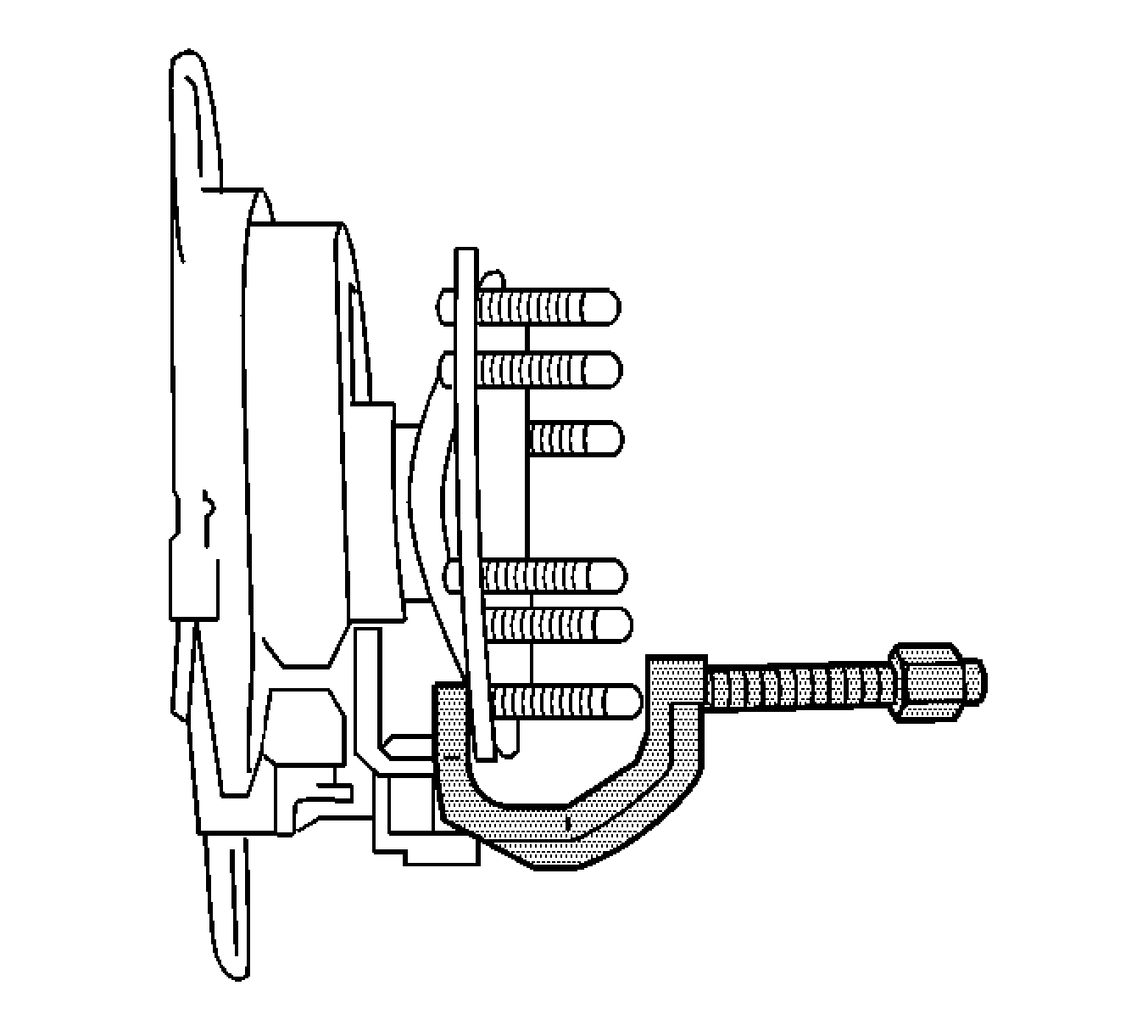
J 43631 Ball Joint Separator
- Raise and support the vehicle. Refer to Lifting and Jacking the Vehicle General Information.
- Remove the tire and wheel assembly. Refer to Tire and Wheel Removal and Installation in Tires and Wheels.
- Remove the caliper. Refer to Rear Brake Caliper Replacement in Disc Brakes.
- Remove the rotor. Refer to Rear Brake Rotor Replacement in Disc Brakes.
- Remove the wheel stud from the axle flange using the J 43631 (15 series).
- Remove the axle shaft (25 series vehicles with 9.5 in ring gear). Refer to Rear Axle Shaft Replacement in Rear Drive Axle.
- Remove the rear hub assembly (25 series vehicles with 10.5 in ring gear). Refer to Hub and Rotor Assembly Replacement in Rear Drive Axle.
- Remove the wheel stud from the axle flange using the J 43631 (25 series vehicles with 9.5 in ring gear).
- Remove the wheel stud from the hub flange using the J 43631 (25 series vehicles with 10.5 in ring gear

Installation Procedure
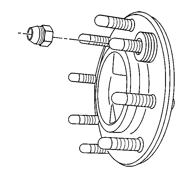
- Install the stud into the axle flange.
- Install the 4 washers and the lug nut to the stud.
- Tighten the lug nut in order to draw the stud into the flange until the stud fully seats.
- Remove the lug nut and the washers.
- Install the axle shaft (25 Series vehicles with 9.5 in ring gear). Refer to Rear Axle Shaft Replacement in Rear Drive Axle.
- Install the rear hub assembly (25 series vehicles with 10.5 in ring gear). Refer to Hub and Rotor Assembly Replacement in Rear Drive Axle.
- Install the rotor. Refer to Rear Brake Rotor Replacement in Disc Brakes.
- Install the caliper. Refer to Rear Brake Caliper Replacement in Disc Brakes.
- Install the tire and wheel assembly. Refer to Tire and Wheel Removal and Installation in Tires and Wheels.
- Remove the safety stands.
- Lower the vehicle.

