Fuel Hose/Pipes Replacement - Chassis 1500 Series
Removal Procedure
Important: Clean all fuel pipe connections and surrounding areas before disconnecting the pipes in order to avoid possible fuel system contamination.
- Relieve the fuel system pressure. Refer to the Fuel Pressure Relief .
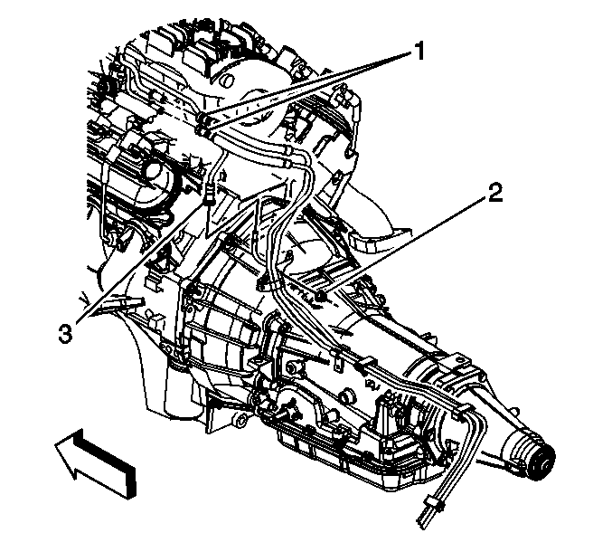
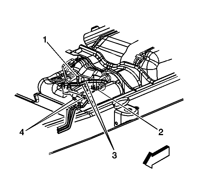
- Disconnect the fuel feed and return pipes (1) at the fuel rail. Refer to Metal Collar Quick Connect Fitting Service .
- Disconnect the evaporative emission (EVAP) canister purge tube (3).
- Cap the fuel rail and EVAP pipes.
- Raise and suitably support the vehicle. Refer to Lifting and Jacking the Vehicle in General Information.
- Unbolt and reposition the front propeller shaft. Refer to Front Propeller Shaft Replacement in Propeller Shaft.
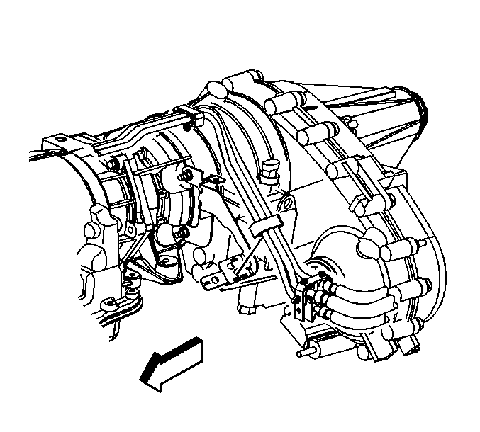
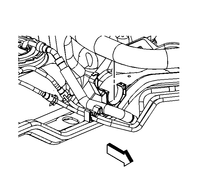
- Remove the fuel pipe bracket nut (2).
- Remove the fuel pipe bracket from the bellhousing stud.
- Remove the fuel hose/pipe clip from the bracket on the automatic transmission.
- If equipped with 4-wheel drive (4WD), remove the fuel hose/pipe clip from the bracket on the transfer case.
- Remove the EVAP canister. Refer to Evaporative Emission Canister Replacement .
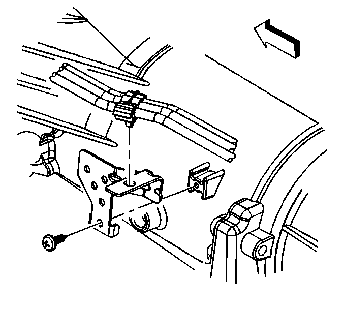
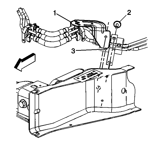
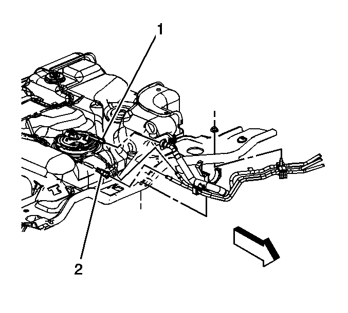
- Remove the fuel filter bracket bolts (2).
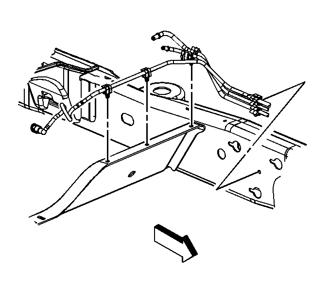
- Remove the fuel pipe/hose bracket (1) bolt.
- Disconnect the fuel feed and return pipes (4) from the fuel tank pipes (3). Refer to Plastic Collar Quick Connect Fitting Service .
- Cap the fuel pipes at the fuel tank.
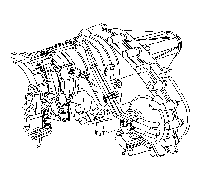
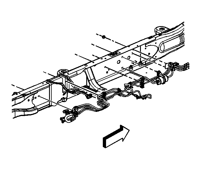
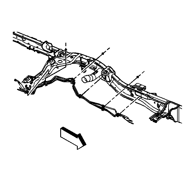
- Remove the fuel hose/pipe clips from the frame and brace.
- Remove the EVAP hose/pipe clips from the brace.
- Remove the fuel pipe/hose assembly.
Installation Procedure
- Install the fuel pipe/hose assembly.
- Install the EVAP hose/pipe clips to the brace.
- Install the fuel hose/pipe clips to the frame and brace.
- Remove the caps from the fuel pipes at the fuel tank.
- Connect the fuel feed and return pipes (4) to the fuel tank pipes (3). Refer to Plastic Collar Quick Connect Fitting Service .
- Insert the integral locator tab (3) into the hole in the frame.
- Install the fuel pipe/hose bracket (1) bolt.
- Install the fuel filter bracket bolts (2).
- Install the EVAP canister. Refer to Evaporative Emission Canister Replacement .
- If equipped with 4WD, install the fuel hose/pipe clip to the bracket on the transfer case.
- Install the fuel hose/pipe clip to the bracket on the automatic transmission.
- Install the fuel pipe bracket to the bellhousing stud.
- Install the fuel pipe bracket nut (2).
- Reposition and install the front propeller shaft bolts. Refer to Front Propeller Shaft Replacement in Propeller Shaft.
- Lower the vehicle.
- Remove the caps from the fuel rail and EVAP pipes.
- Connect the EVAP canister purge tube (3).
- Connect the fuel feed and return pipes (1) at the fuel rail. Refer to Metal Collar Quick Connect Fitting Service .
- Install the fuel fill cap.
- Connect the negative battery cable. Refer to Battery Negative Cable Disconnection and Connection in Engine Electrical.
- Use the following procedure in order to inspect for leaks:
Notice: Use the correct fastener in the correct location. Replacement fasteners must be the correct part number for that application. Fasteners requiring replacement or fasteners requiring the use of thread locking compound or sealant are identified in the service procedure. Do not use paints, lubricants, or corrosion inhibitors on fasteners or fastener joint surfaces unless specified. These coatings affect fastener torque and joint clamping force and may damage the fastener. Use the correct tightening sequence and specifications when installing fasteners in order to avoid damage to parts and systems.
Tighten
Tighten the bolt to 12 N·m (106 lb in).
Tighten
Tighten the bolts to 12 N·m (106 lb in).
Tighten
Tighten the nut to 10 N·m (89 lb in).
| 21.1. | Turn the ignition ON, with the engine OFF, for 2 seconds. |
| 21.2. | Turn the ignition OFF for 10 seconds. |
| 21.3. | Turn the ignition ON, with the engine OFF. |
| 21.4. | Inspect for fuel leaks. |
Fuel Hose/Pipes Replacement - Chassis 2500 Series - Front
Removal Procedure
Important: Clean all fuel pipe connections and surrounding areas before disconnecting the pipes in order to avoid possible fuel system contamination.
- Relieve the fuel system pressure. Refer to Fuel Pressure Relief .
- Disconnect the fuel feed and return pipe (1) at the fuel rail. Refer to Metal Collar Quick Connect Fitting Service .
- Disconnect the evaporative emission (EVAP) canister purge tube (3).
- Cap the fuel rail and fuel/EVAP pipes.
- Raise and suitably support the vehicle. Refer to Lifting and Jacking the Vehicle in General Information.
- Remove the fuel pipe bracket nut (2).
- Remove the fuel pipe bracket from the bellhousing stud.
- Remove the fuel hose/pipe clip from the bracket on the automatic transmission.
- If equipped with 4-wheel drive (4WD), remove the fuel hose/pipe clip from the bracket on the transfer case.
- Remove the front fuel tank. Refer to Fuel Tank Replacement .
- Disconnect the front fuel lines from the rear fuel lines. Refer to Plastic Collar Quick Connect Fitting Service .
- Remove the fuel line bracket nuts.
- Remove the fuel/EVAP pipe/hose assembly.
Installation Procedure
- Insert the fuel/EVAP pipe/hose assembly.
- Install the fuel line bracket nuts.
- Install the front fuel tank. Refer to Fuel Tank Replacement .
- If equipped with 4WD, install the fuel hose/pipe clip to the bracket on the transfer case.
- Install the fuel hose/pipe clip to the bracket on the automatic transmission.
- Install the fuel pipe bracket to the bellhousing stud.
- Install the fuel pipe bracket nut (2).
- Lower the vehicle.
- Remove the caps from the fuel rail and fuel/EVAP pipes.
- Connect the EVAP canister purge tube (3).
- Connect the fuel feed and return pipe (1) to the fuel rail. Refer to Metal Collar Quick Connect Fitting Service .
- Install the fuel fill cap.
- Connect the negative battery cable. Refer to Battery Negative Cable Disconnection and Connection in Engine Electrical.
- Use the following procedure in order to inspect for leaks:
Notice: Refer to Fastener Notice in the Preface section.
Tighten
Tighten the bolt to 12 N·m (106 lb in).
Tighten
Tighten the nut to 10 N·m (89 lb in).
| 14.1. | Turn the ignition ON, with the engine OFF, for 2 seconds. |
| 14.2. | Turn the ignition OFF for 10 seconds. |
| 14.3. | Turn the ignition ON, with the engine OFF. |
| 14.4. | Inspect for fuel leaks. |
Fuel Hose/Pipes Replacement - Chassis 2500 Series - Rear
Removal Procedure
Important: Clean all fuel pipe connections and surrounding areas before disconnecting the pipes in order to avoid possible fuel system contamination.
- Relieve the fuel system pressure. Refer to Fuel Pressure Relief .
- Raise and suitably support the vehicle. Refer to Lifting and Jacking the Vehicle in General Information.
- Open the retaining clip.
- Remove the hose from the clip.
- Remove the evaporative emission (EVAP) and fuel pipes from the clip.
- Disconnect the EVAP tubes (2). Refer to Plastic Collar Quick Connect Fitting Service .
- Disconnect the fuel pipe at the sending unit (1). Refer to Metal Collar Quick Connect Fitting Service .
- Remove the front fuel tank. Refer to Fuel Tank Replacement .
- Disconnect the front fuel lines from the rear fuel lines. Refer to Plastic Collar Quick Connect Fitting Service .
- Cap the fuel/EVAP pipes.
- Remove the fuel line bracket nuts.
- Remove the fuel/EVAP pipe/hose assembly.
Installation Procedure
- Install the fuel/EVAP pipe/hose assembly.
- Install the fuel line bracket nuts.
- Remove the caps from the fuel/EVAP pipes.
- Connect the front fuel lines to the rear fuel lines. Refer to Plastic Collar Quick Connect Fitting Service .
- Install the front fuel tank. Refer to Fuel Tank Replacement .
- Connect the fuel pipe to the sending unit (1). Refer to Metal Collar Quick Connect Fitting Service .
- Connect the EVAP tubes (2). Refer to Plastic Collar Quick Connect Fitting Service .
- Install the EVAP and fuel pipes to the clip.
- Install the hose to the clip.
- Close the retaining clip.
- Lower the vehicle.
- Install the fuel fill cap.
- Connect the negative battery cable. Refer to Battery Negative Cable Disconnection and Connection in Engine Electrical.
- Use the following procedure in order to inspect for leaks:
Notice: Refer to Fastener Notice in the Preface section.
Tighten
Tighten the nuts to 12 N·m (106 lb in).
| 14.1. | Turn the ignition ON, with the engine OFF, for 2 seconds. |
| 14.2. | Turn the ignition OFF for 10 seconds. |
| 14.3. | Turn the ignition ON, with the engine OFF. |
| 14.4. | Inspect for fuel leaks. |
