Removal Procedure
Important: The intake manifold, throttle body, fuel rail, and injectors may be removed as an assembly. If not servicing the individual components, remove the manifold as a complete assembly.
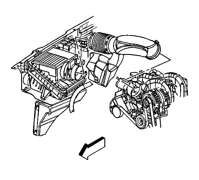
- Loosen the clamps at the throttle body and air cleaner.
- Remove the air cleaner outlet duct.
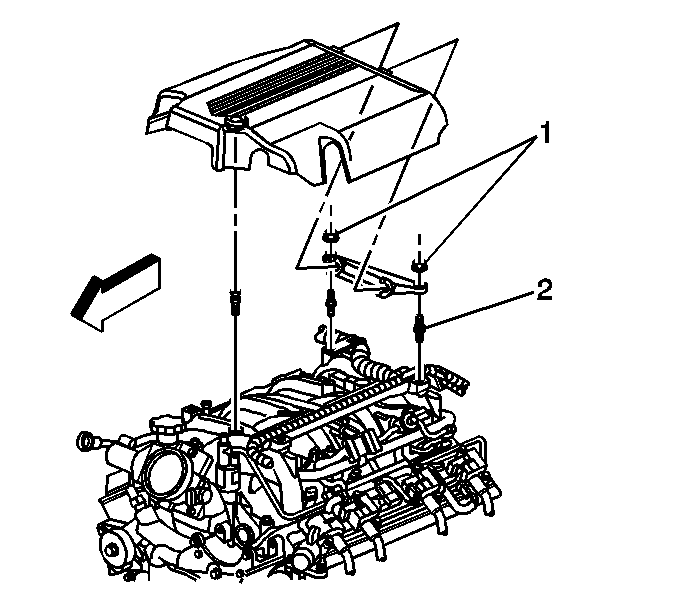
- Unsnap the intake manifold sight shield from the stud.
- Remove the sight shield from the bracket.
- Remove the sight shield bracket nuts (1) and bracket, if necessary.
- Relieve the fuel system pressure. Refer to
Fuel Pressure Relief
.
- Disconnect the fuel feed and return pipes. Refer to
Metal Collar Quick Connect Fitting Service
.
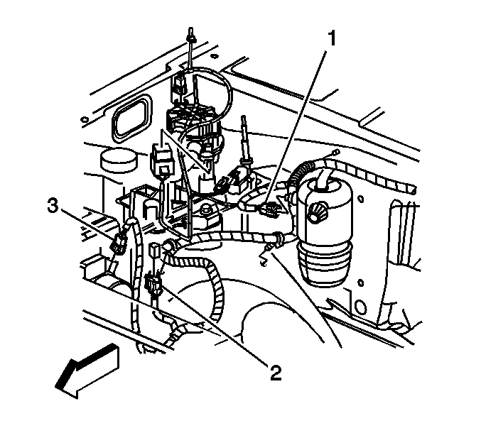
- Disconnect the engine harness clips from the studs on the front of dash.
- Disconnect the engine harness clip from the wheelhouse splash shield.
- Disconnect the following electrical connectors:
| • | Pressure cycling switch (1) |
| • | Mass airflow (MAF) sensor (3) |
- Reposition the engine harness branch to top of engine.
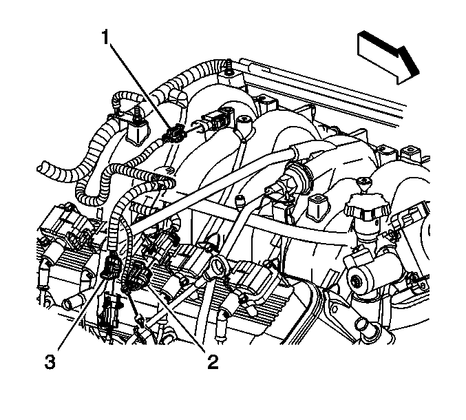
- Remove the connector position assurance (CPA) retainer at the ignition coil harness.
- Disconnect the following electrical connectors:
| • | Manifold absolute pressure (MAP) sensor (1) |
| • | Ignition coil harness (2) |
| • | Engine coolant temperature (ECT) sensor (3) |
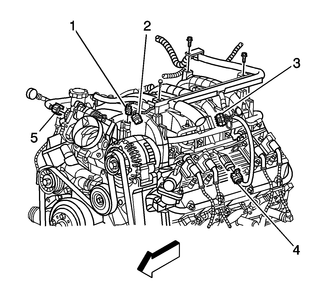
- Remove the engine harness bolt and studs
- Remove the CPA retainer at the ignition coil harness.
- Disconnect the following electrical connectors:
| • | Ignition coil harness (4) |
| • | Electronic throttle control (ETC) (5) |
| • | Purge valve solenoid (1) |
- Reposition the engine harness to the drivers side of the engine compartment.
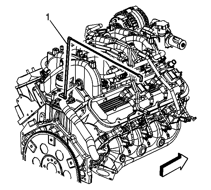
- Remove the bypass valve vacuum hose (1) from the intake manifold.
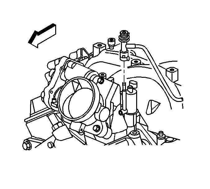
- Disconnect the evaporative emission (EVAP) tube from the purge solenoid.
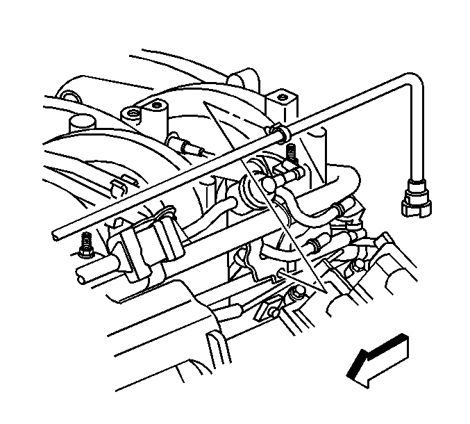
- Unclip the EVAP tube from the fuel rail.
- Disconnect the EVAP tube from the vent pipe at the rear of the engine.
- Remove the EVAP tube.
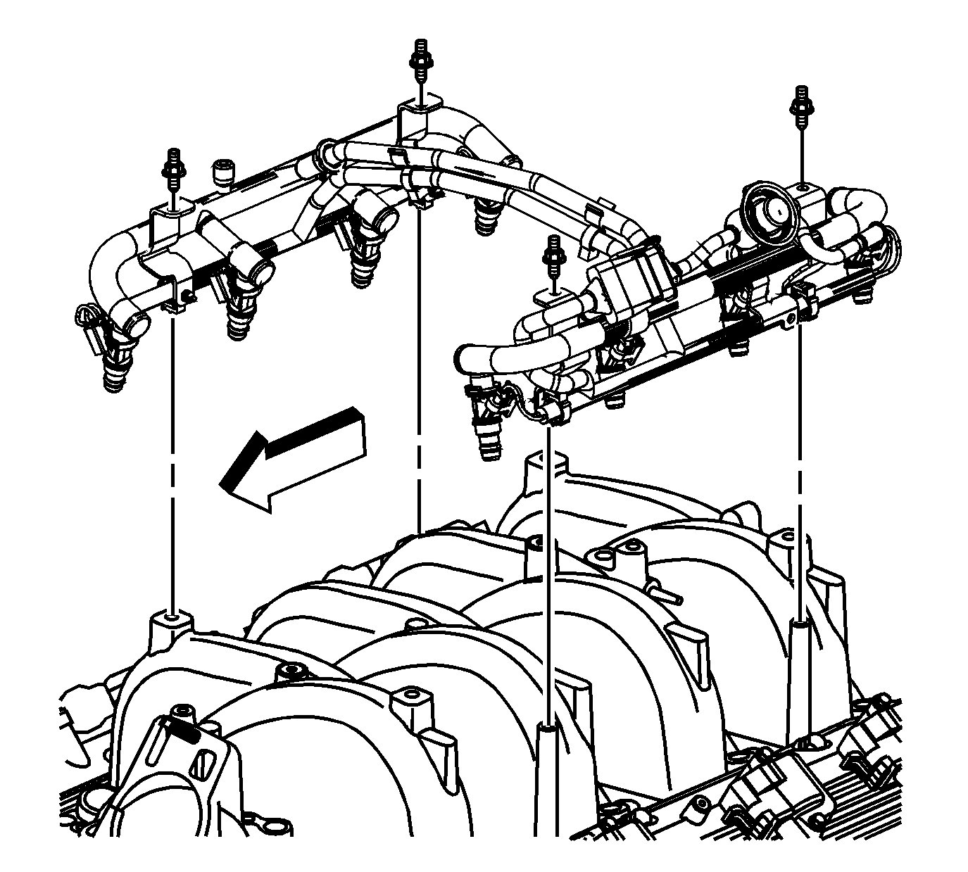
- If replacing the intake manifold, remove the fuel rail studs.
- Remove the fuel rail.
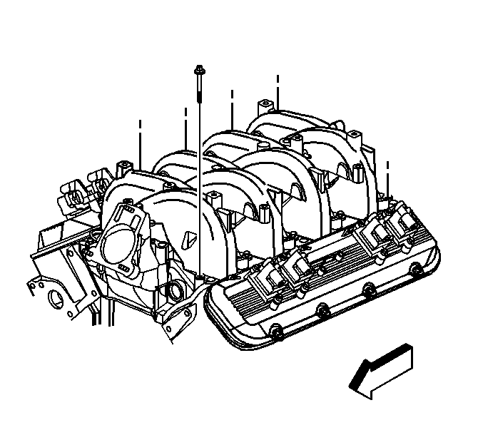
Important: Do not attempt to loosen the manifold by prying under the gasket surface with any tool.
- Remove the intake manifold bolts.
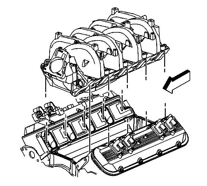
- Remove the intake manifold.
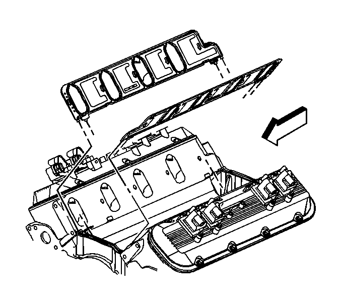
Important: The intake manifold gaskets are not reusable.
- Remove and discard the intake manifold side gaskets.
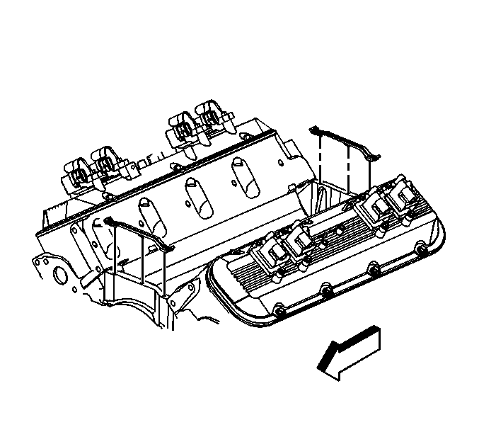
- Remove and discard the intake manifold end seals.
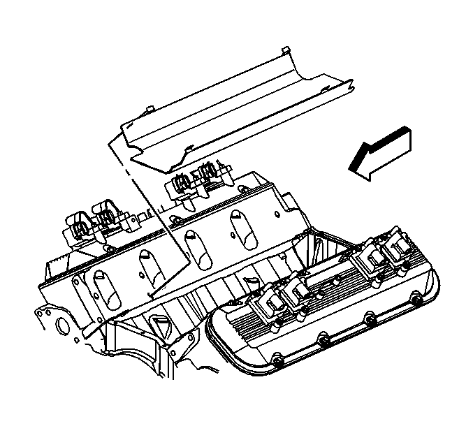
Important: The splash shield is secured using a snap-in fit. Do not distort the splash shield. The splash shield is reusable.
- Remove the splash shield.
- If replacing the intake manifold, refer to
Intake Manifold Disassemble
.
- Clean and inspect the intake manifold. Refer to
Intake Manifold Cleaning and Inspection
.
Installation Procedure

- If replacing the intake manifold, refer to
Intake Manifold Assemble
.
- Install the splash shield.
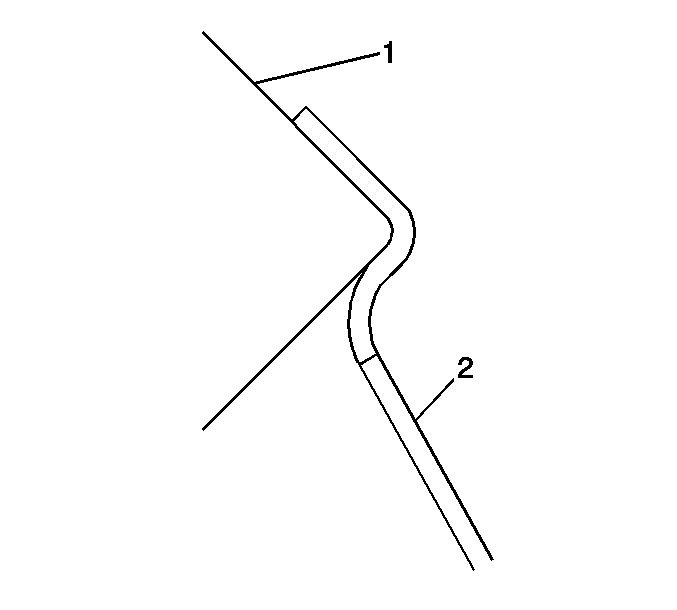
- Ensure the splash shield (2) snap fits between the cylinder heads (1).
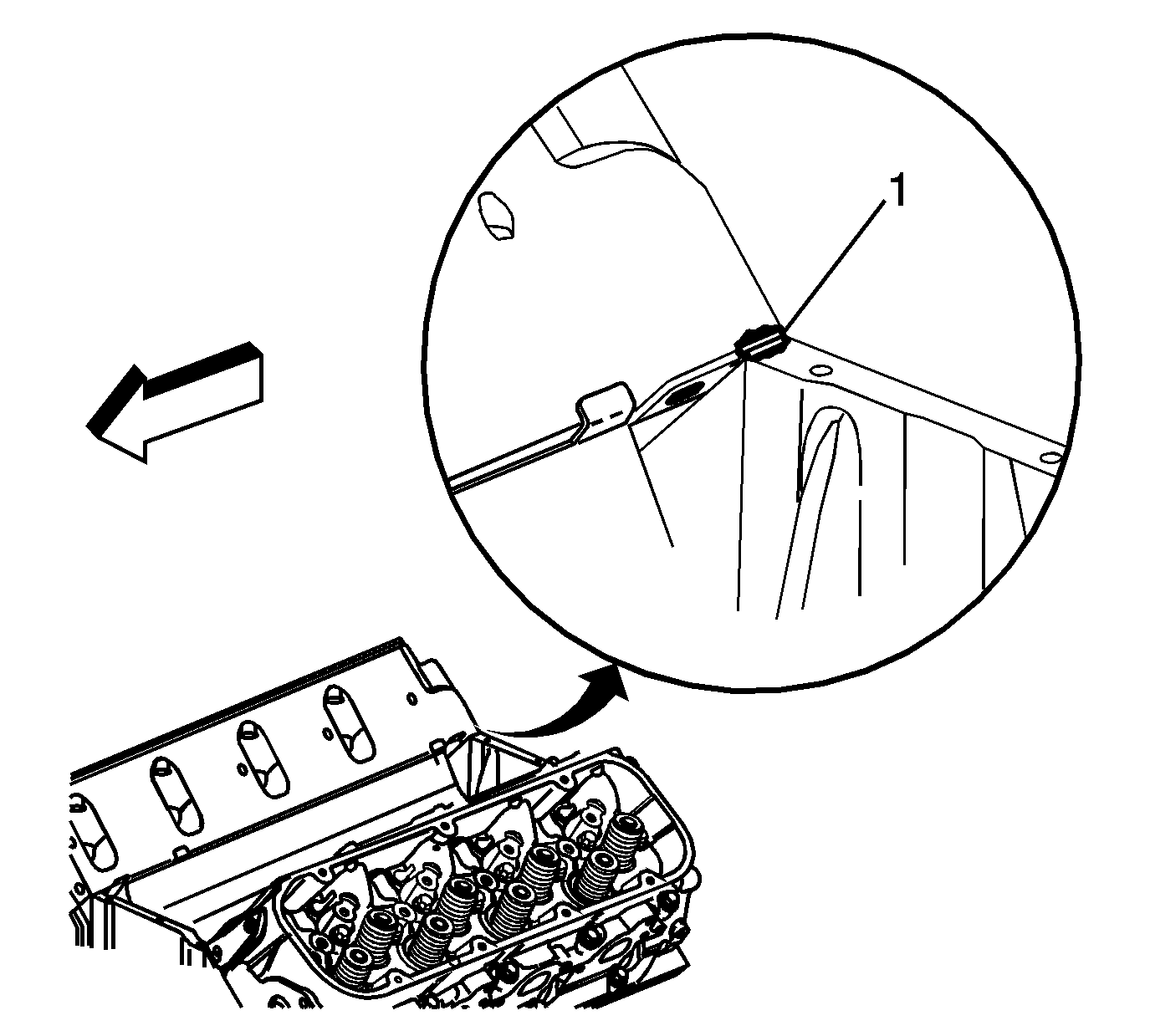
- Apply a 5 mm (0.2 in) bead of sealer to
the intake manifold. Refer to
Adhesives, Fluids, Lubricants, and Sealers
for the correct part number.

- Install the NEW intake manifold end seals.
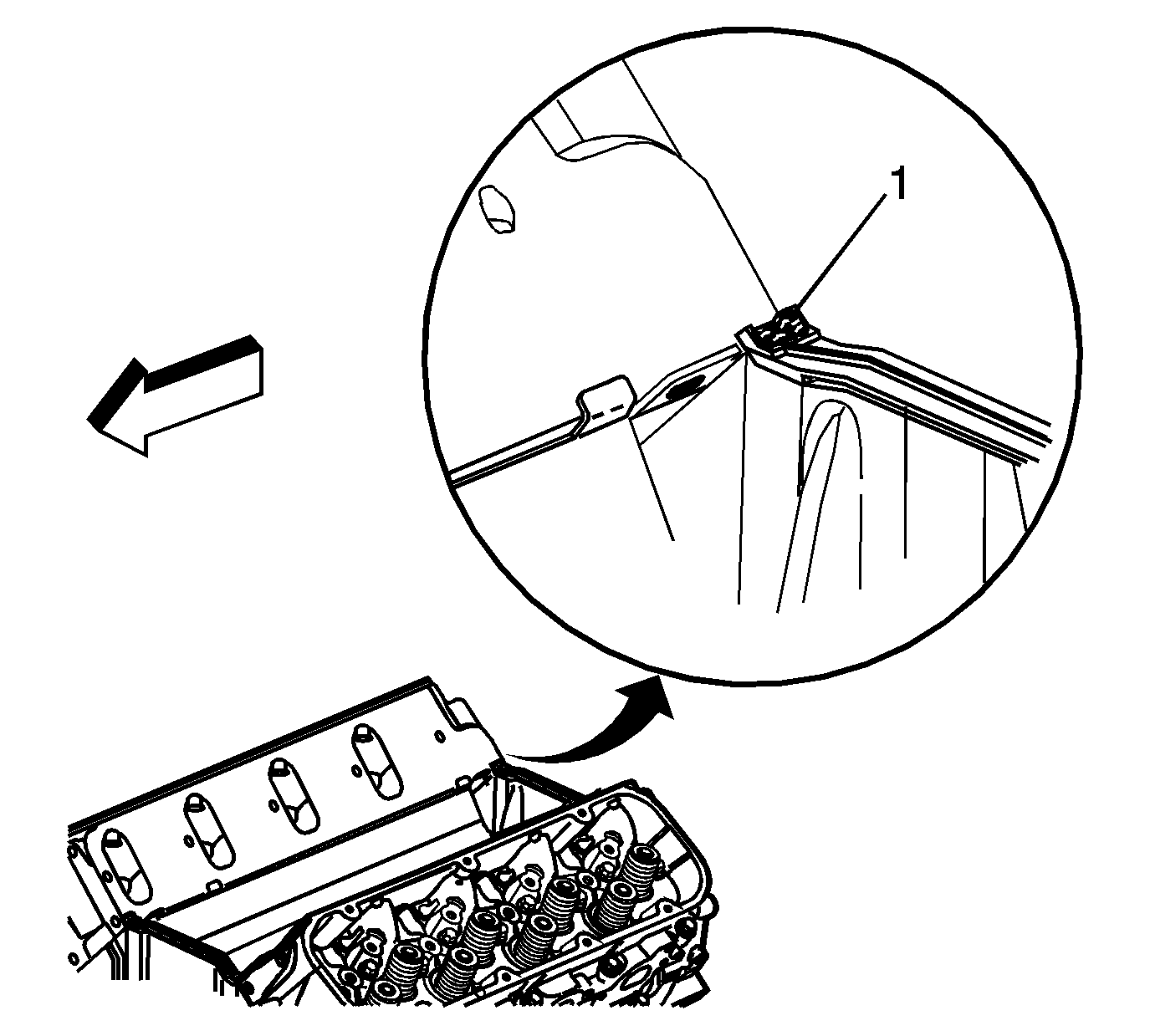
- Apply a 5 mm (0.2 in) bead of sealer (1)
onto the end seals. Refer to
Adhesives, Fluids, Lubricants, and Sealers
for the correct part number.

- Install the NEW intake manifold side gaskets.
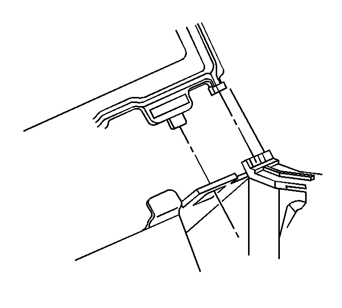
- Ensure the intake manifold gasket tabs align with the hole in the head gasket.
- Ensure the intake manifold gasket tabs align with the slot in the intake manifold end seals.

- Install the intake manifold.

- Install NEW intake manifold bolts.
Notice: Refer to Fastener Notice in the Preface section.
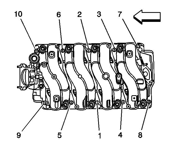
- Tighten the intake manifold bolts in the sequence shown, using 4 passes.
Tighten
- Tighten the bolts a first pass to 5 N·m (44 lb in).
- Tighten the bolts a second pass to 8 N·m (71 lb in).
- Tighten the bolts a third pass to 12 N·m (106 lb in).
- Tighten the bolts a final pass to 15 N·m (11 lb ft).

Important: Lubricate the fuel injector O-ring seals with clean engine oil and install onto the spray tip of each injector.
- If replacing the intake manifold, install the fuel rail.
- Install the fuel rail studs.
Tighten
Tighten the studs to 12 N·m (106 lb in).

- Install the EVAP tube.
- Connect the EVAP tube to the vent pipe at the rear of the engine.
- Clip the EVAP tube to the fuel rail.

- Connect the EVAP tube to the purge solenoid.

- Install the bypass valve vacuum hose (1) to the intake manifold.

- Position the engine harness over the engine compartment.
- Connect the following electrical connectors:
| • | Ignition coil harness (4) |
| • | Purge valve solenoid (1) |
- Install the CPA retainer at the ignition coil harness.
- Install the engine harness bolt and studs.
Tighten
| • | Tighten the bolt to 16 N·m (12 lb ft). |
| • | Tighten the studs to 10 N·m (89 lb in). |

- Connect the following electrical connectors:
| • | Ignition coil harness (2) |
- Install the CPA retainer at the ignition coil harness.

- Position engine harness branch over the top of engine.
- Connect the following electrical connectors:
| • | Pressure cycling switch (1) |
- Connect the engine harness clip to the wheelhouse splash shield.
- Connect the engine harness clips to the studs on the front of dash.

- Connect the fuel feed and return pipes.
- Install the sight shield bracket and nuts (1).
Tighten
Tighten the nuts to 5 N·m (44 lb in).
- Install the sight shield to the bracket.
- Snap the intake manifold sight shield to the stud.

- Install the air cleaner outlet duct.
- Tighten the clamps at the throttle body and air cleaner.
Tighten
Tighten the clamps to 4 N·m (35 lb in).


