Removal Procedure
Important: The redesigned frame of the 1500 model C/K pickup and C/K Utility, incorporates hydroformed technology. There is a replaceable, hydroformed, energy absorbing crush cap at the front of the frame.
- Disable the SIR system. Refer to SIR Disabling and Enabling .
- Disconnect the negative battery cable. Refer to Battery Negative Cable Disconnection and Connection .
- Remove all of the related panels and the components.
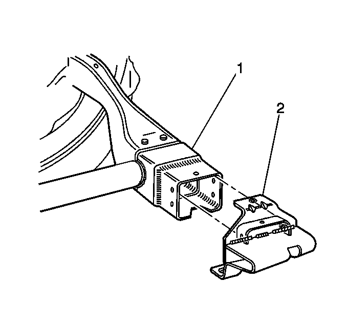
- Visually inspect the damage. Use 3-dimensional measuring in order to restore all of the damage rearward of the crush cap (1) to the factory specifications.
- Remove the core support mounting bracket (2).
- Locate the brake line attachment hole (1) on the top of the rail. Measure forward 155 mm (6 1/8 in). This is the cut line (2).
- Scribe a line 360 degrees around the frame rail.
- Remove the crush cap at the cut-line and the forward edge of the cross tube.
- Grind the remaining weld off of the cross tube (1) where you removed the damaged crush cap.
Caution: Refer to Approved Equipment for Collision Repair Caution in the Preface section.
Caution: Refer to Collision Sectioning Caution in the Preface section.
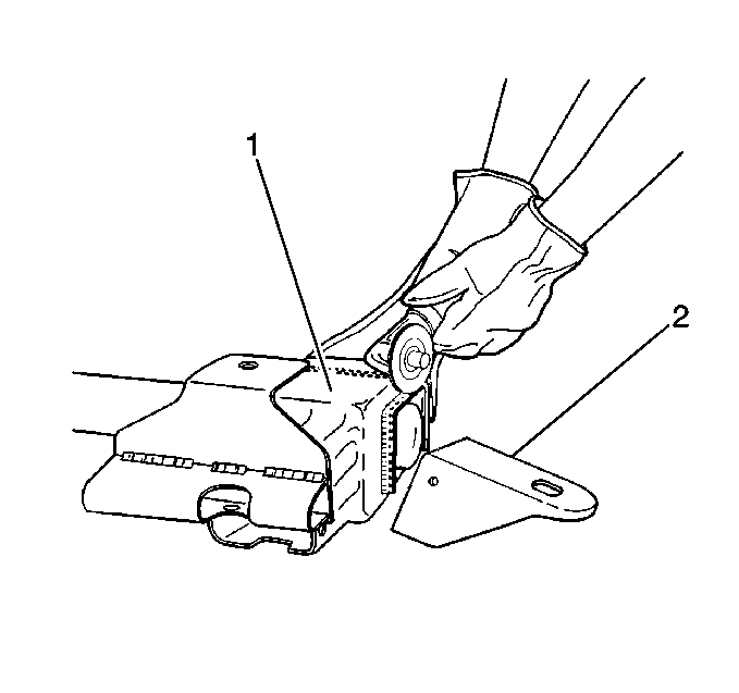
Important: If the crush cap (1) is bent or damaged in any way, replace the crush cap.
Important: Do not damage the rail.
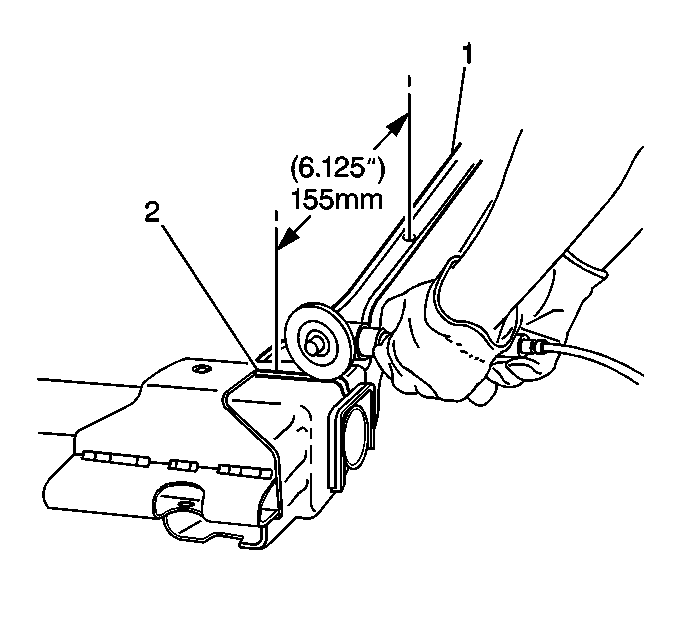
Important: Use caution to not damage the cross tube.
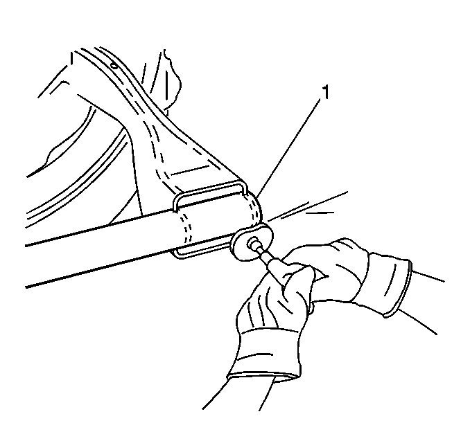
Installation Procedure
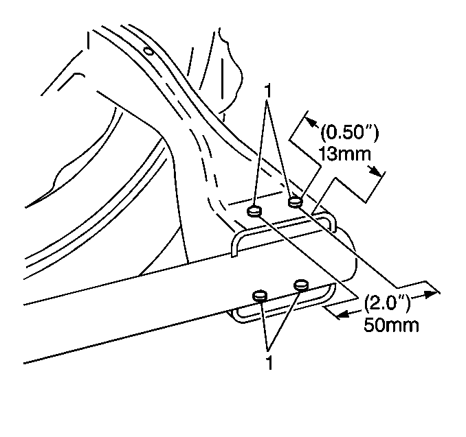
- Drill 4 plug weld holes; 2 at the top and 2 at the bottom, 13 mm (1/2 in) from the cut line and 50 mm (2 in) apart on the existing frame rail (1).
- Prepare all mating surfaces as necessary.
- Apply 3M Weld-Thru Coating P/N 05916 or equivalent to all mating surfaces.
- Install and position the replacement crush cap using 3-dimensional measuring.
- Tack weld the part into position at the initial plug weld holes.
- Inspect the service part for proper dimensions.
- Stitch weld along the entire sectioning joint. Make 25 mm (1 in) welds along the seam with 25 mm (1 in) gaps between.
- Complete the stitch weld.
- Clean and prepare the welded surfaces.
- Apply approved anti-corrosion primer.
- Position the new core support mounting bracket. Weld the bracket in place according to the specified dimensions.
- Apply the sealers.
- Refinish the welded surfaces as necessary.
- Replace the related panels and the components.
- Connect the negative battery cable. Refer to Battery Negative Cable Disconnection and Connection .
- Enable the SIR system. Refer to SIR Disabling and Enabling .
Important:
• The replacement bumper bracket (2) is a bolt-on component that must be ordered separately. • Retain a gap of 1½ times the metal thickness at the butt joint (1) when attaching the service part to the vehicle.
Important: Prior to refinishing, refer to GM 4901MD-99 Refinish Manual for recommended products. Do not combine paint systems. Refer to paint manufacturer's recommendations.
