For 1990-2009 cars only
Removal Procedure
- If equipped with a Bose™ amplifier, remove the radio amp fuse located under the hood electrical center. Refer to Electrical Center Identification Views.
- Remove the floor console bezel. Refer to Floor Console Bezel Replacement.
- Remove the cupholder. Refer to Cupholder Replacement.
- Remove the bolts (1) retaining the console to the instrument panel (I/P).
- Remove the console storage bin. Refer to Front Floor Console Compartment Replacement.
- Remove the center console end panel. Refer to Center Console End Panel Replacement in Instrument Panel, Gages and Console.
- Disconnect the audio amplifier electrical connectors.
- Remove the 4 screws retaining the upper console bracket to the lower console bracket.
- Move both front seats to the fully forward.
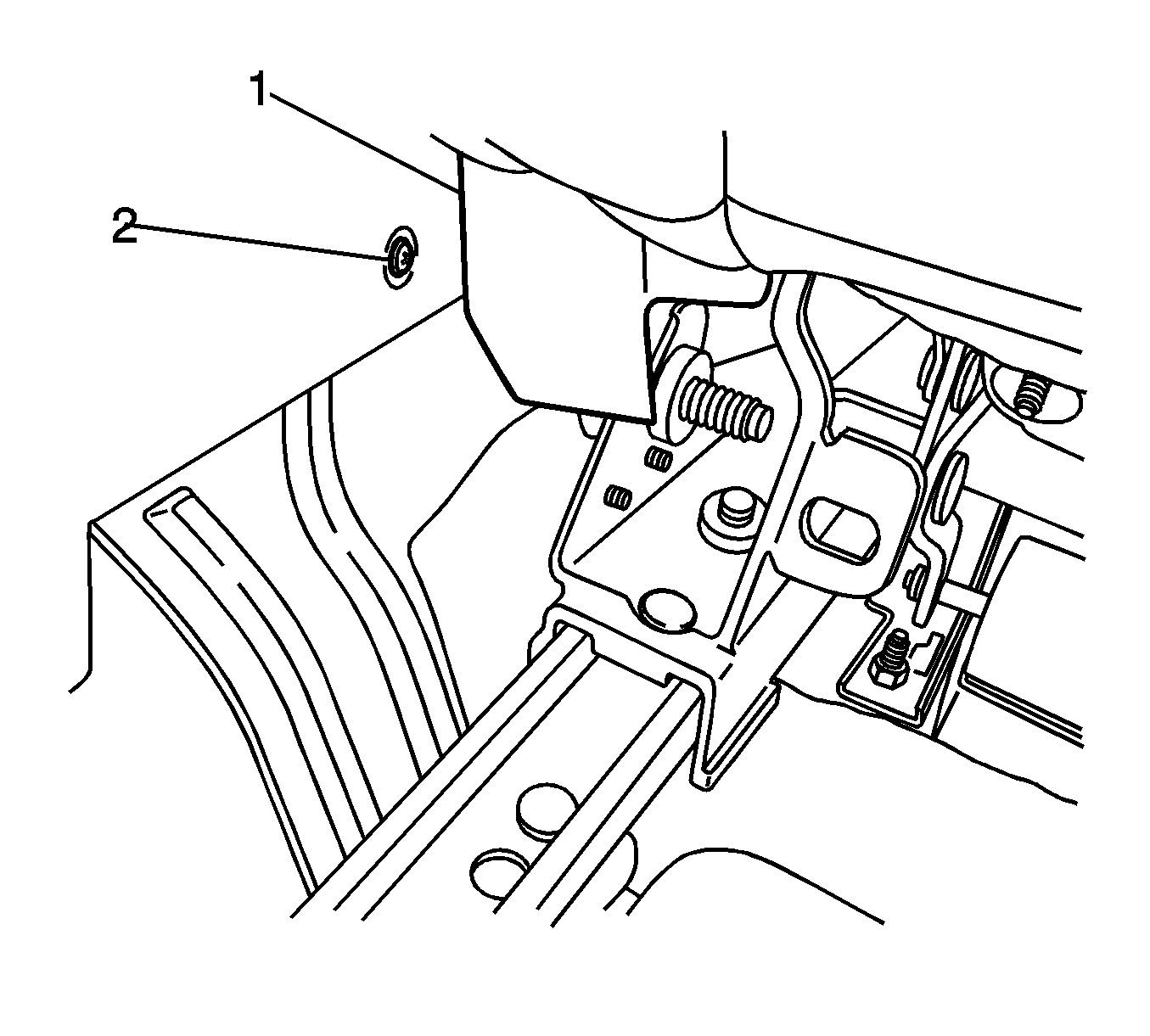
- Reposition the inboard seat track trim (1) in order to gain access to the rear console side panel screw (2).
- Remove both rear console side panel screws.
- Move both front seats to the fully rearward.
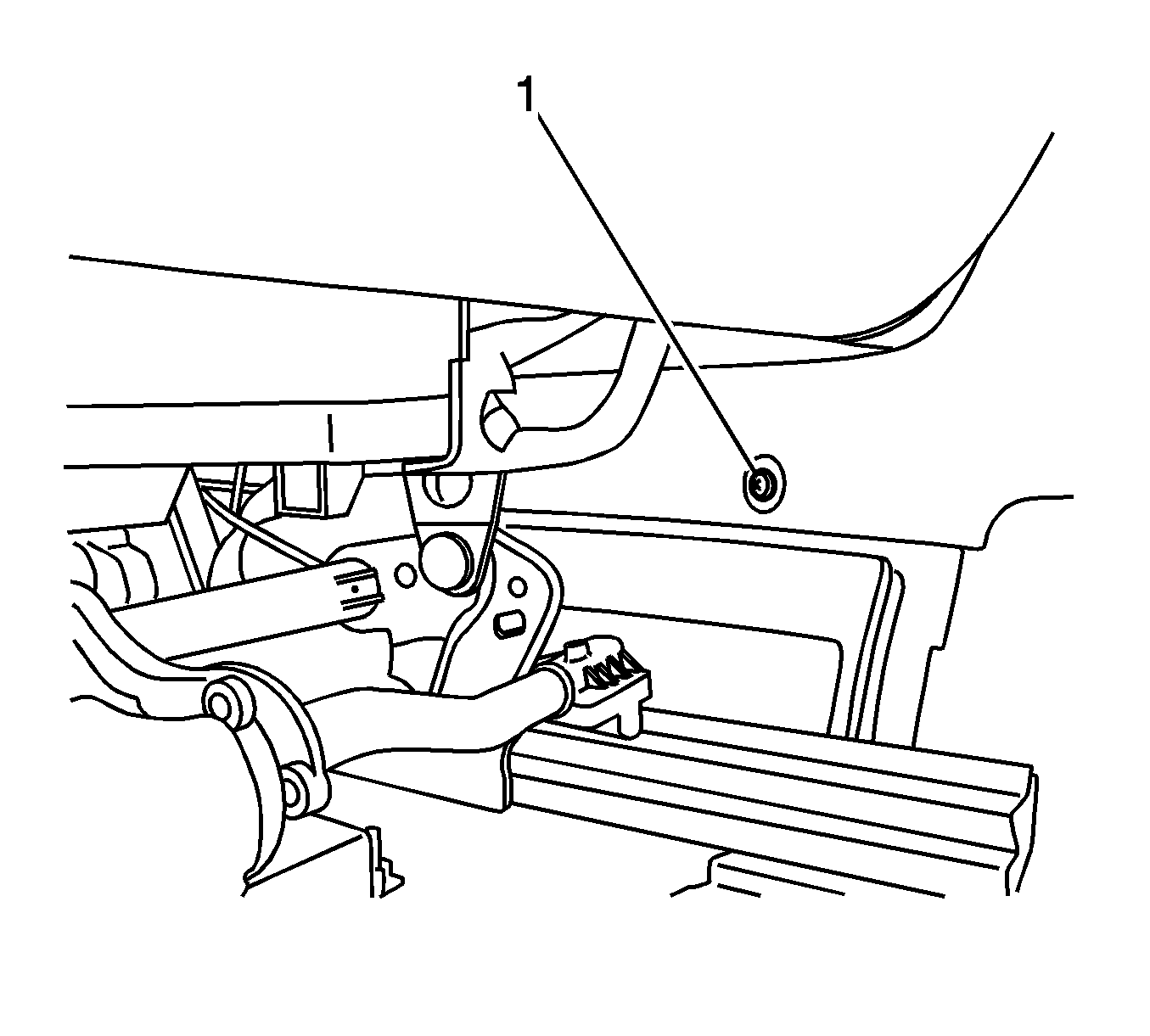
- Remove both front console side panel screws (1).
- Disconnect the floor console electrical connector.
- Remove the console assembly from the vehicle.
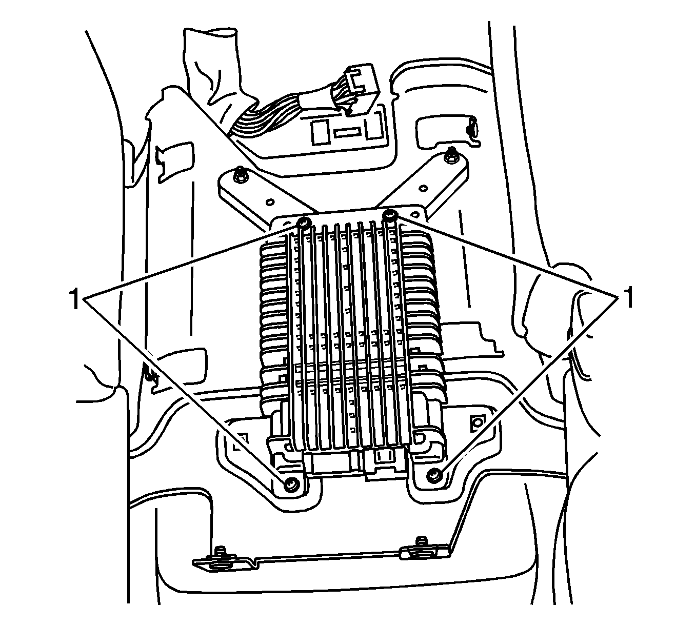
- Remove the audio amplifier screws (1).
- Remove the audio amplifier from the vehicle.
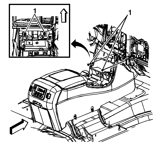
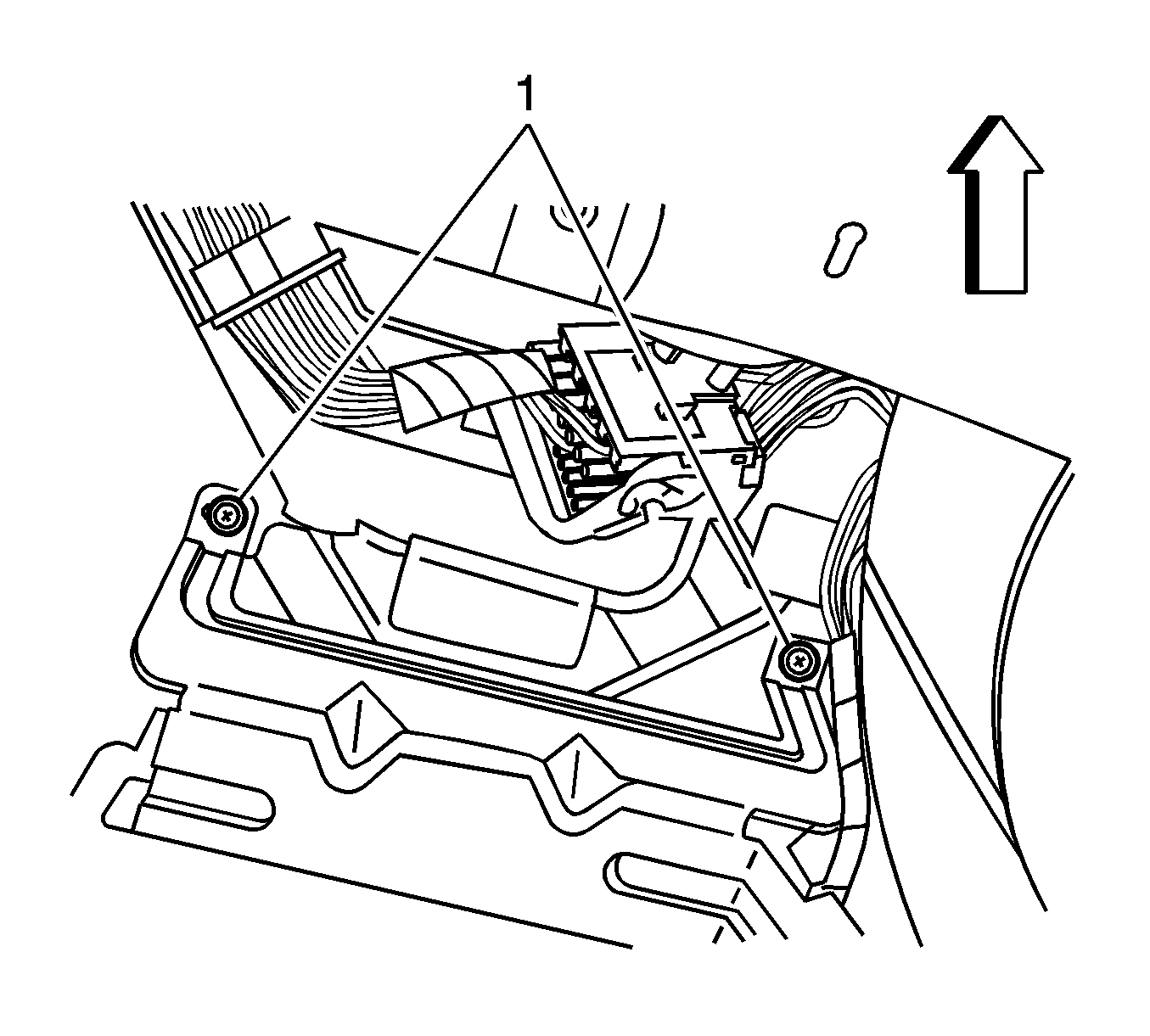
The front 2 screws (1) are shown in the graphic.
Installation Procedure
- Install the audio amplifier to the floor console lower bracket.
- Install the amplifier screws.
- Install the floor console.
- Connect the floor console electrical connector.
- Install the screws (1) that retaining the upper console bracket to the lower console bracket.
- Install the bolts (1) retaining the console to the I/P.
- Install both front console side panel screws (1).
- Move both front seats to the fully forward.
- Install both rear console side panel screws (2).
- Reposition the inboard seat track trim (1).
- Connect the audio amplifier electrical connectors.
- Connect the floor console electrical connector.
- Install the center console end panel. Refer to Center Console End Panel Replacement.
- Install the console storage bin. Refer to Front Floor Console Compartment Replacement.
- Install the cupholder to the console. Refer to Cupholder Replacement in Instrument Panel, Gages and Console.
- Install the upper console bezel. Refer to Floor Console Bezel Replacement.
- Install the radio amp fuse. Refer to Electrical Center Identification Views.
- If the amplifier has been replaced, perform the audio amplifier set up procedure for the BOSE™ amplifier with UQ7 and Y91. Refer to Audio Amplifier Setup .
- Refer to Control Module References for programming and setup information.
Notice: Refer to Fastener Notice in the Preface section.
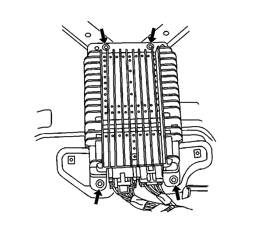
Tighten
Tighten the screws to 3.4 N·m (30 lb in).

Tighten
Tighten the retaining screws to 2 N·m (18 lb in).
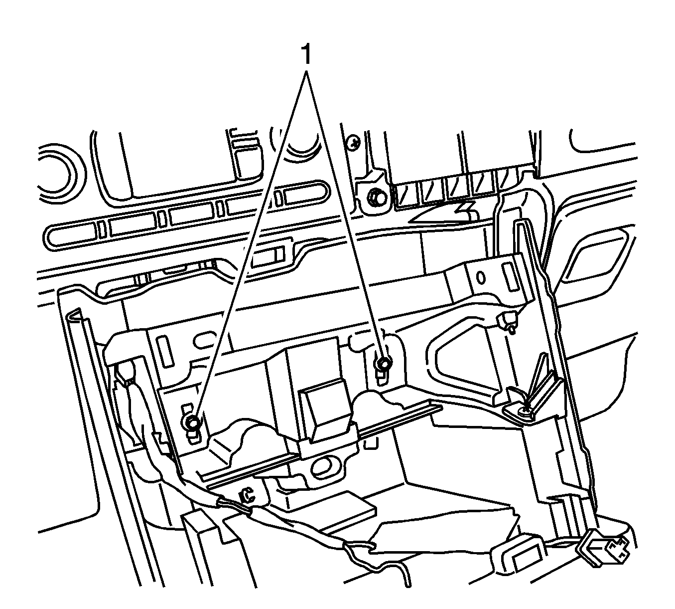
Tighten
Tighten the bolts to 4 N·m (35 lb in).

Tighten
Tighten the screws to 2 N·m (18 lb in).

Tighten
Tighten the retaining screws to 2 N·m (18 lb in).
