For 1990-2009 cars only
Disassembly Procedure
Tools Required
| • | J 8092 Universal Driver Handle |
| • | J 36370 Drive Sprocket Needle Bearing Installer |
| • | J 29170 Drive Sprocket Bearing Remover |
| • | J 29369 Output Shaft Bearing Remover |
| • | J 9276-21 Adapter |
| • | J 2619-01 Slide Hammer |
| • | J 33790 Input Sungear Needle Bearing Installer |
- Use solvent and a stiff brush to clean the exterior of the transfer case.
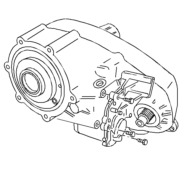
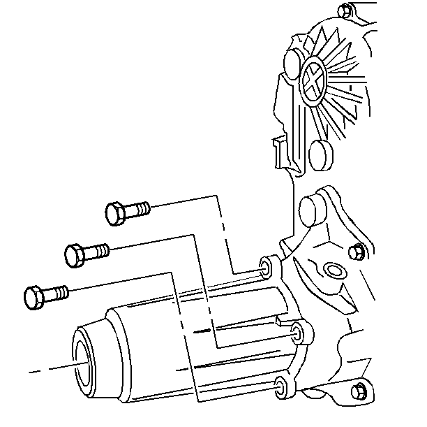
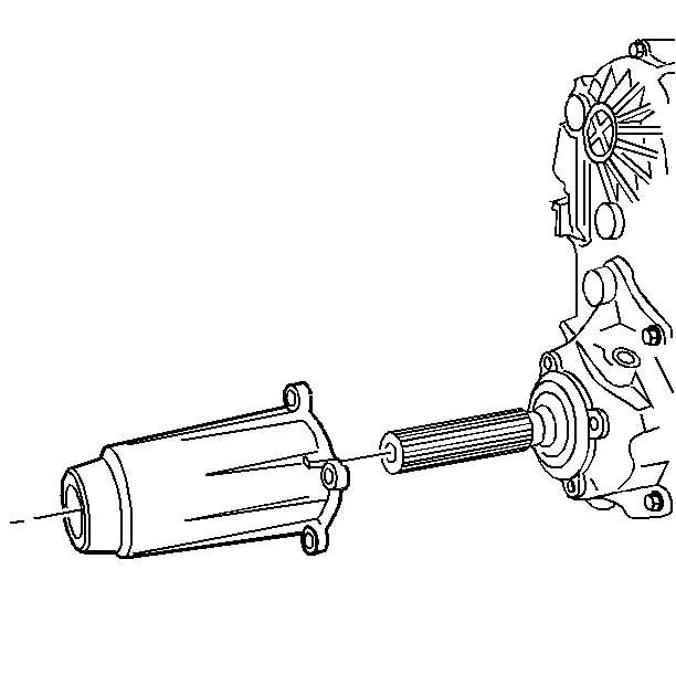
- Remove the shift motor bolts.
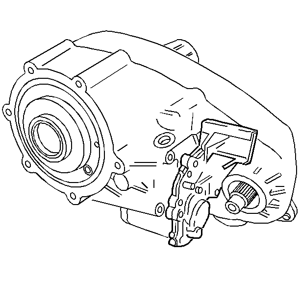
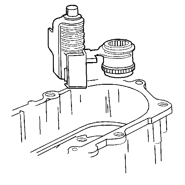
- Remove the shift motor.
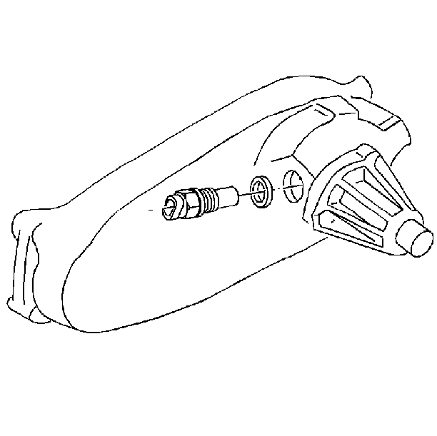
- Remove the vehicle speed sensor.
- Remove the speed sensor O-ring from the sensor.
- Remove the vacuum switch and its O-ring.
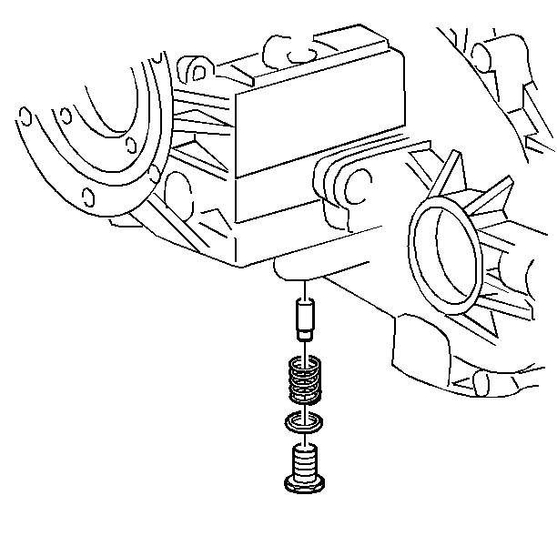
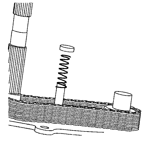
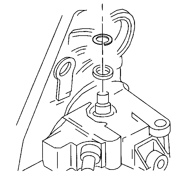
- Remove the detent plug, spring, and plunger.
- Remove the rear extension housing bolts.
- Remove the rear extension housing. Tap the extension housing with a rubber hammer in order to free it from the sealer.
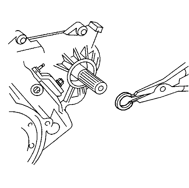
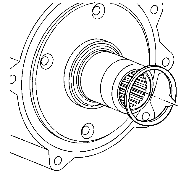
- Remove the rear bearing retainer snap ring.
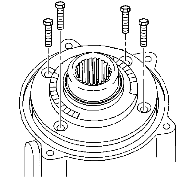
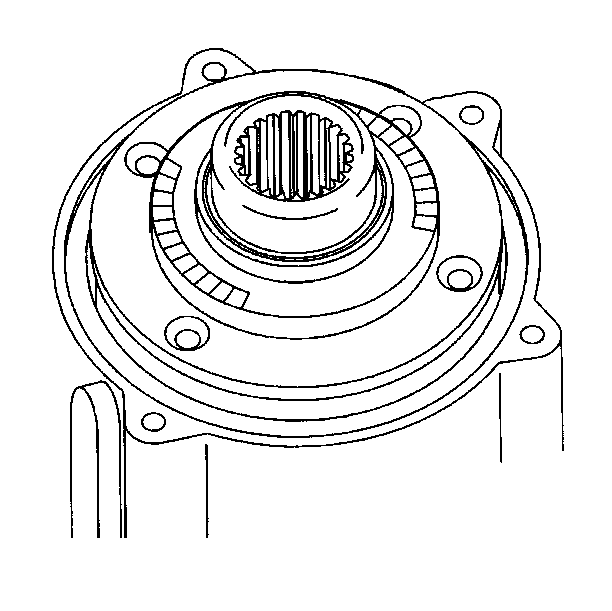
- Remove the rear retainer housing bolts.
- Remove the rear retainer housing. Carefully pry upward under each tab on the retainer housing.
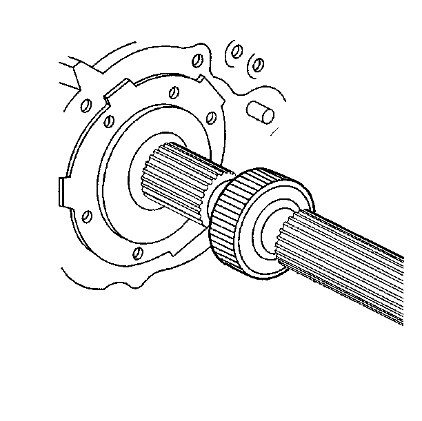
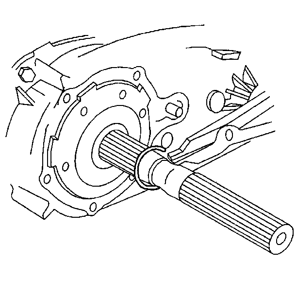
- Remove the vehicle speed sensor rotor snap ring.
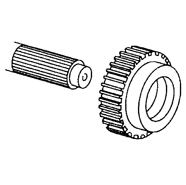
- Remove the vehicle speed sensor rotor.
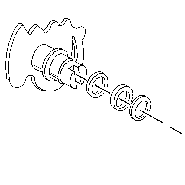
- Remove the snap ring from the mainshaft.
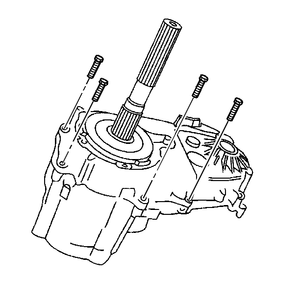
- Remove the case bolts. The two longer case bolts and washers go into the doweled holes.
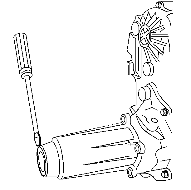
- Separate the case halves.
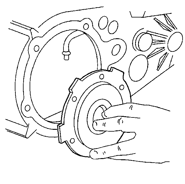
- Remove the oil pump.
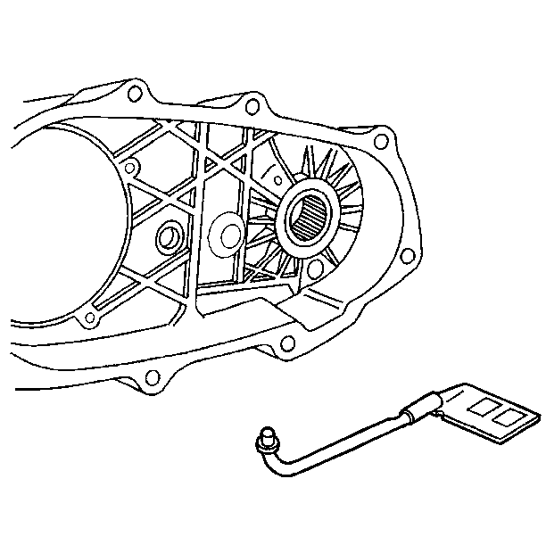
- Remove the oil pump pickup tube, O-ring, and pump pickup filter.
- Remove the mode shift fork spring.
- Remove the front output shaft seal.
- Remove the front output shaft snap ring.
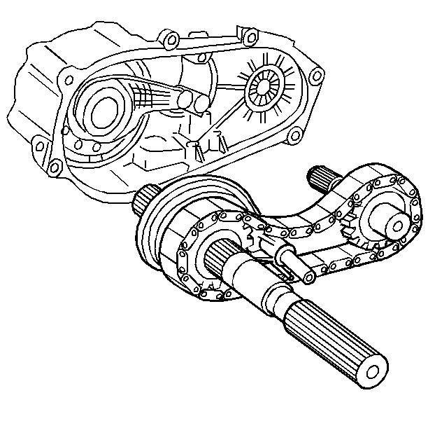
- Remove the mainshaft, drive chain, and driven sprocket assembly. The mode shift fork and the shift rail will be removed with the mainshaft.
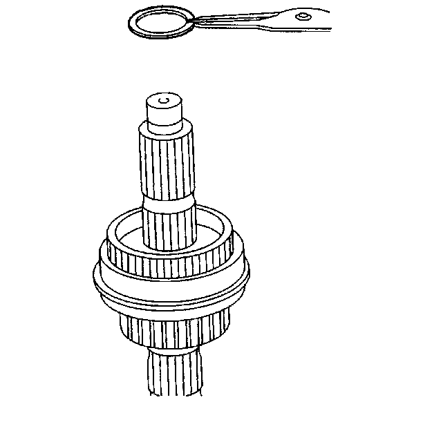
- Remove the synchronizer to mainshaft snap ring.
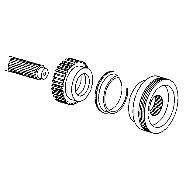
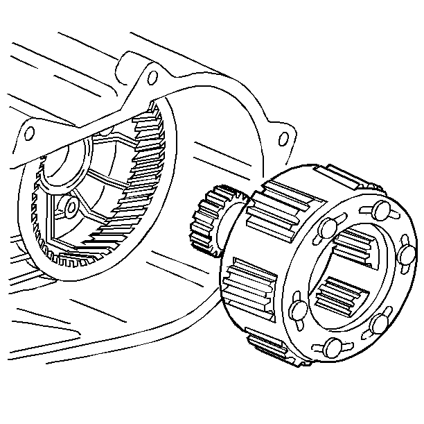
- Remove the synchronizer assembly.
- Remove the drive sprocket.
- Remove the shift fork and range shift hub. Rotate the sector shaft in order to obtain clearance for the range fork.
- Remove the shift sector snap ring.
- Remove the sector shaft assembly.
- Remove the input bearing retainer bolts.
- Remove the input bearing retainer.
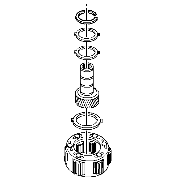
- Remove the input gear snap ring.
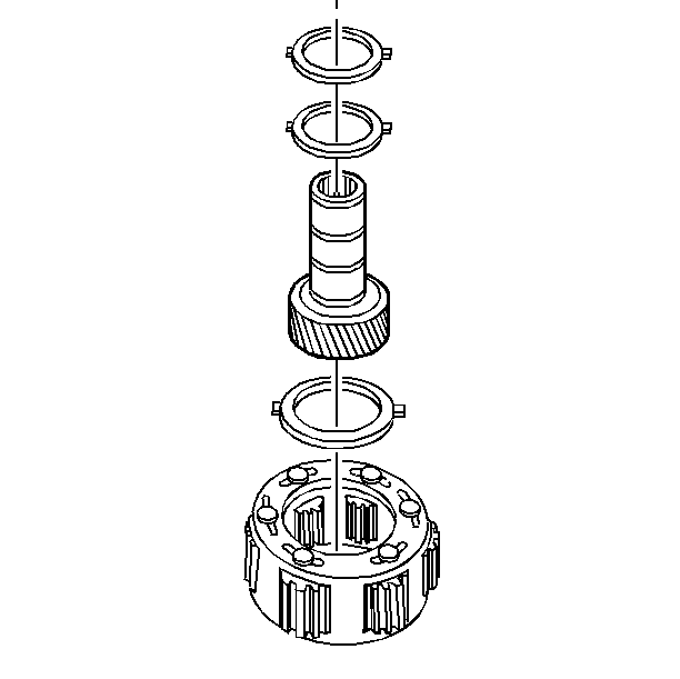
- Use a soft face hammer in order to remove the input and low range gear assembly.
- Remove the input gear to low range gear assembly snap ring.
- Separate the input gear from the low range gear assembly.
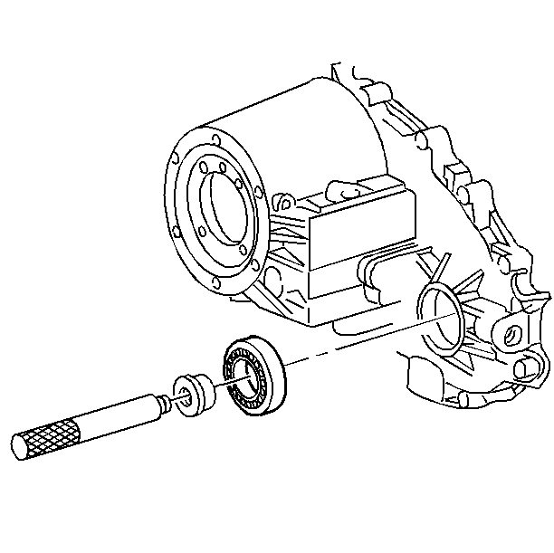
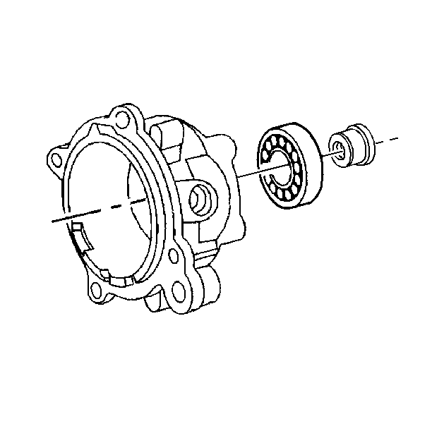
- Use the J 36370 and the J 8092 in order to remove the input bearing.
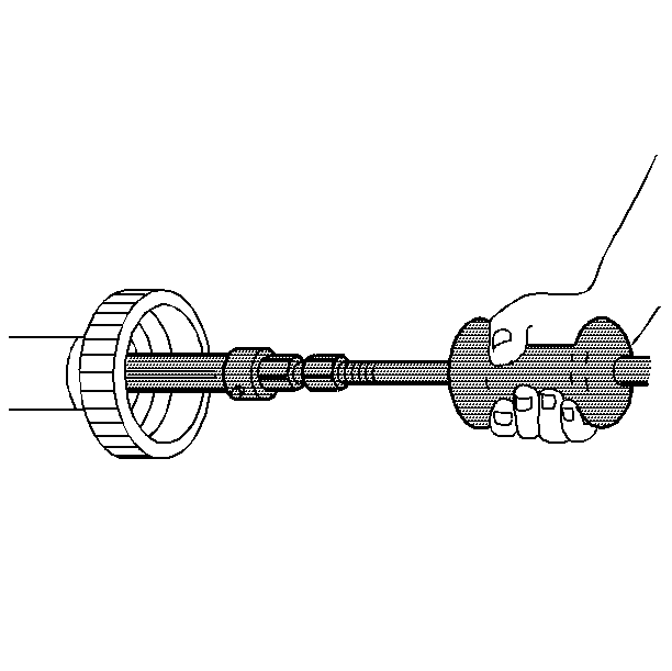
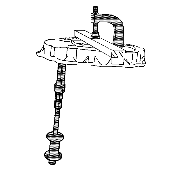
- Use the J 29369 , the J 9276-21 , and the J 2619-01 in order to remove the needle bearings from the input gear.
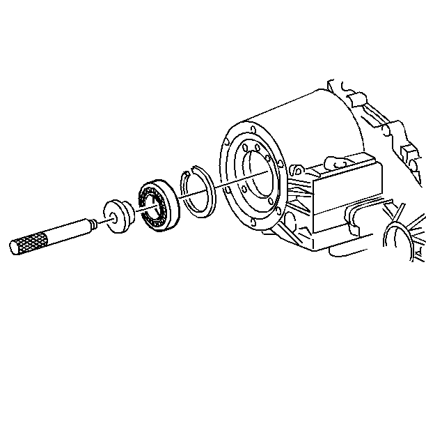
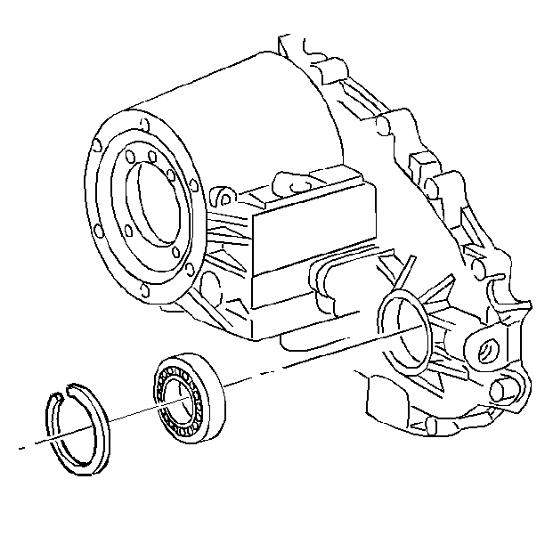
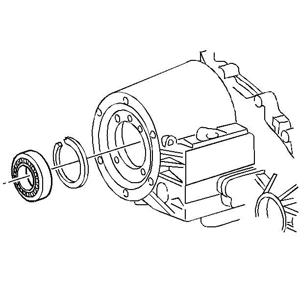
- Remove the front output bearing snap ring.
- Use the J 33790 and the J 8092 in order to remove the front output bearing.
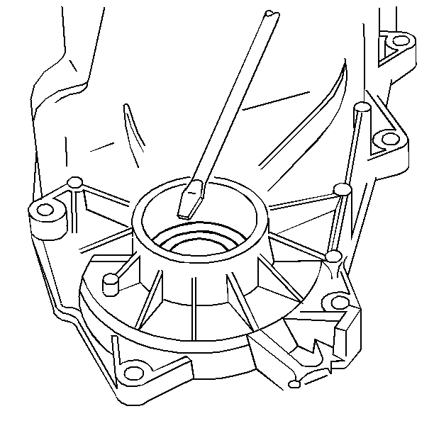
- Remove the seal from the mainshaft extension housing.
- Remove the input bearing retainer seal.
- Use the J 2619-01 and the J 29369-2 in order to remove the front output rear bearing.
- Use the J 33790 in order to remove the mainshaft bearing from the oil pump retainer.
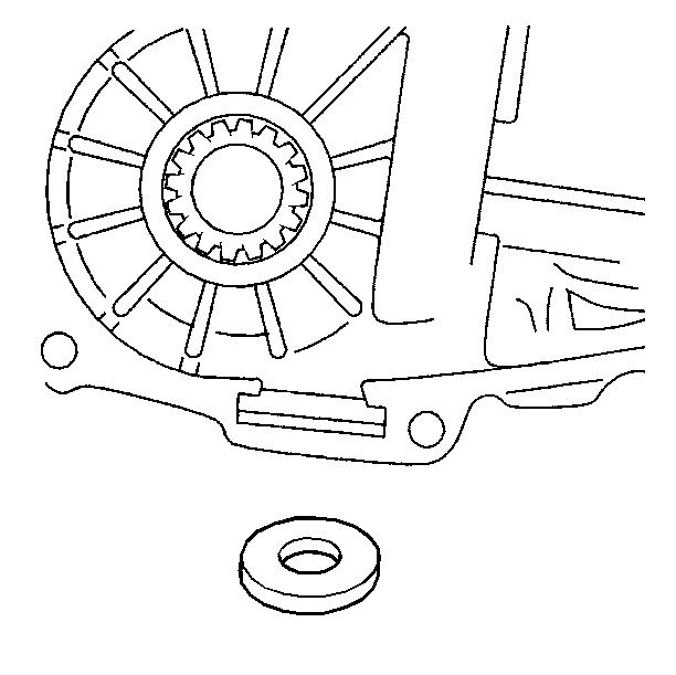
- Remove the magnet from the front case.
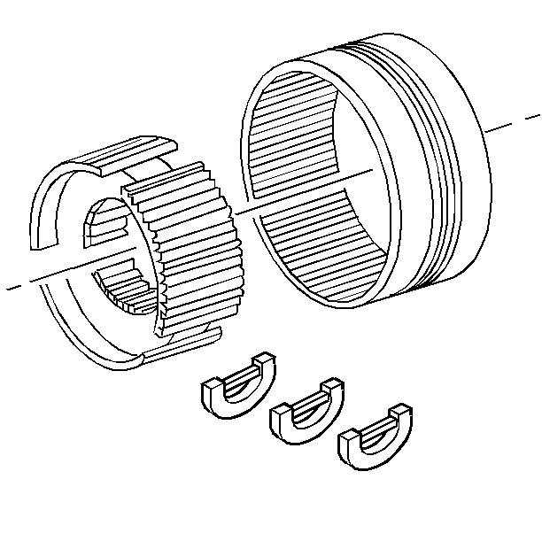
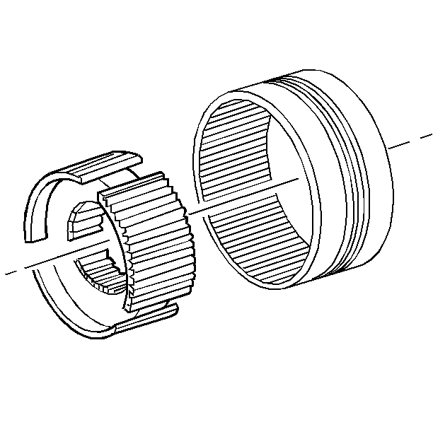
- Disassemble the main drive synchronizer stop rings from the synchronizer sleeve.
- Remove the spring retainers from the synchronizer hub.
- Separate the synchronizer hub from the synchronizer.
- Remove the oil pump screws from the oil pump.
Important:
• The annulus gear found in this transfer case is not serviceable
or removed. The gear should only be replaced as a unit with the front case
half. Damage will occur to the case if the gear is removed. • The oil pump is not a serviceable unit and should be replaced
if it is defective.
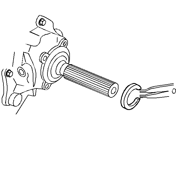
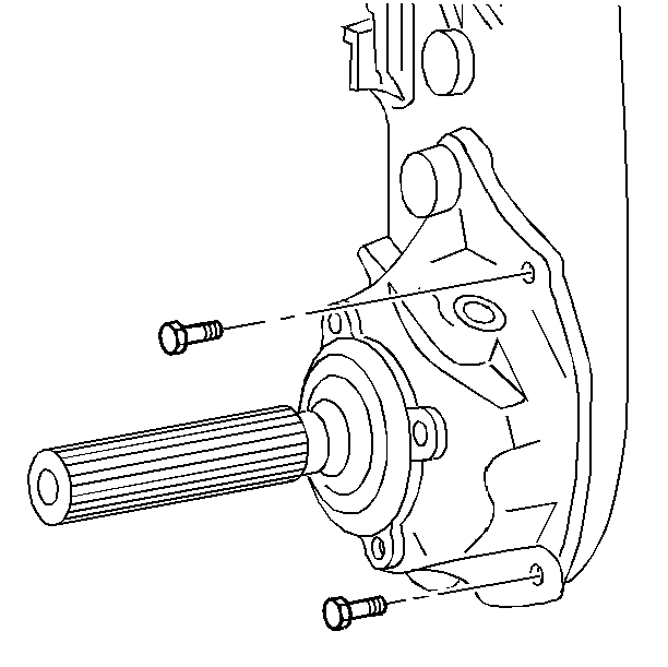
Important: Do not pry against the sealing surfaces.
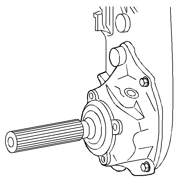
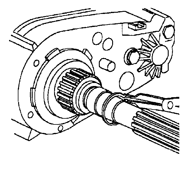
Important: Some transfer case models have a bracket attached to them by the case bolts. These bolts are different from the others and must be returned into the correct holes.
Important: Damage may occur if you attempt to pry the case halves apart at any point on the mating surfaces.
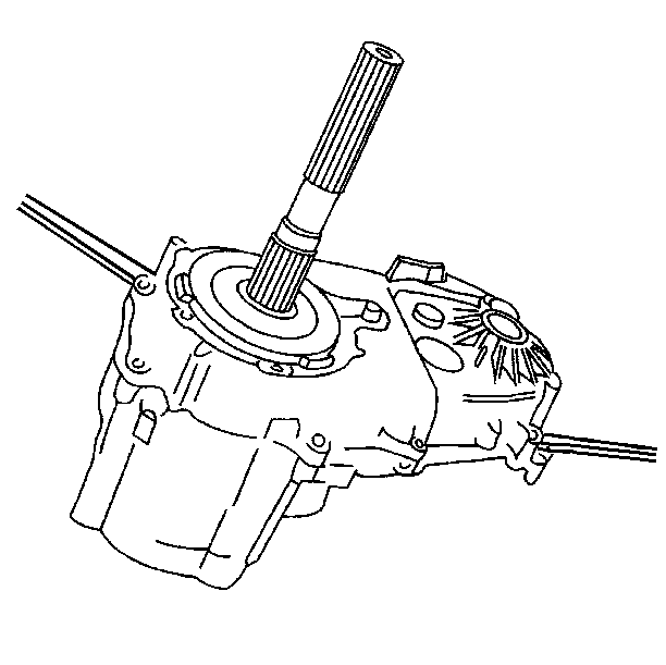
| • | Insert screwdrivers into the slots that are molded into the case ends and pry apart. |
| • | Do not damage the oil pump on the rear case half. |
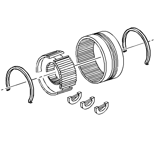
| • | Mark the location of the synchronizer hub and sleeve. |
| • | The synchronizer teeth must align with the struts. |
