Assembly Procedure
Tools Required
| • | J 8092 Universal Driver Handle |
| • | J 33833 Front Case Bearing Installer |
| • | J 36372 Input Sungear Needle Bearing Installer |
| • | J 33843 Rear Extension Seal Installer |
| • | J 33831 Input Seal Installer |
| • | J 33832 Bearing Installer |
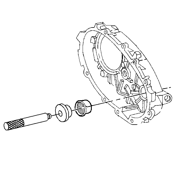
- Use the J 33832 and the J 8092 in order to install the needle bearings. The bearing must be flush with the boss on the case housing.
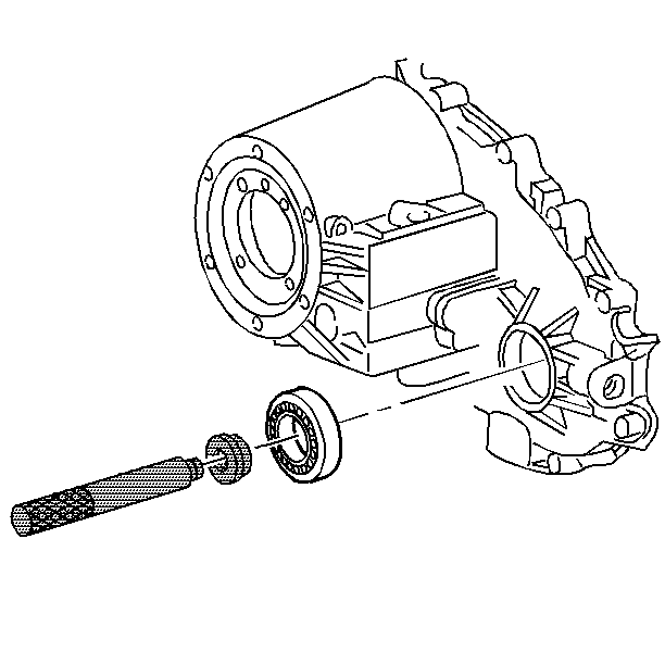
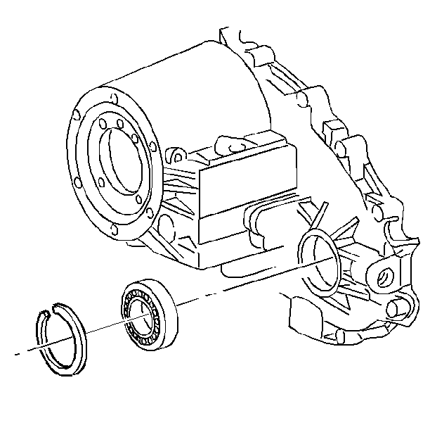
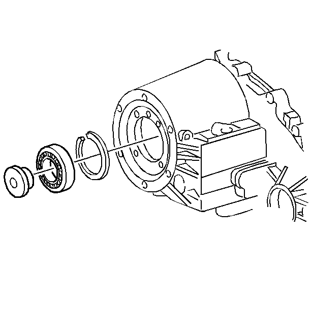
- Use the J 33833 and the J 8092 in order to install the front output bearing.
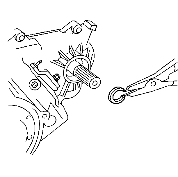
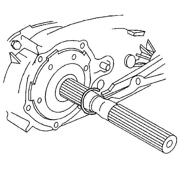
- Install the front output bearing snap ring.
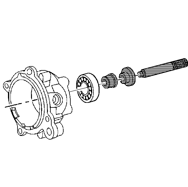
- Use the J 33833 and the J 8092 in order to install the bearing into the rear retainer housing.
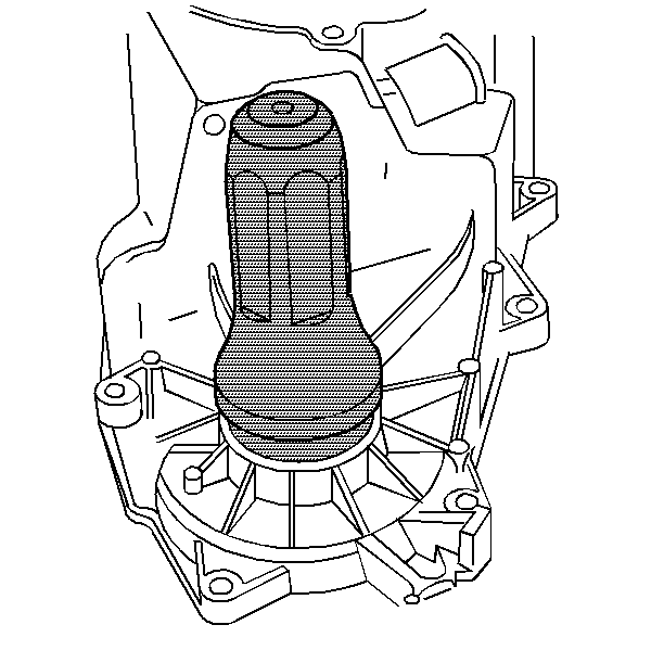
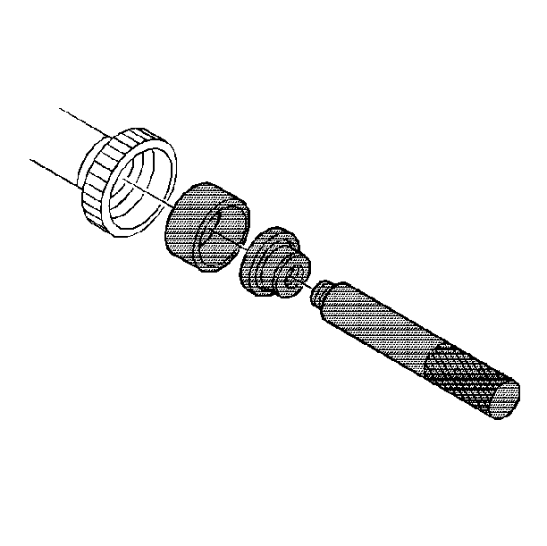
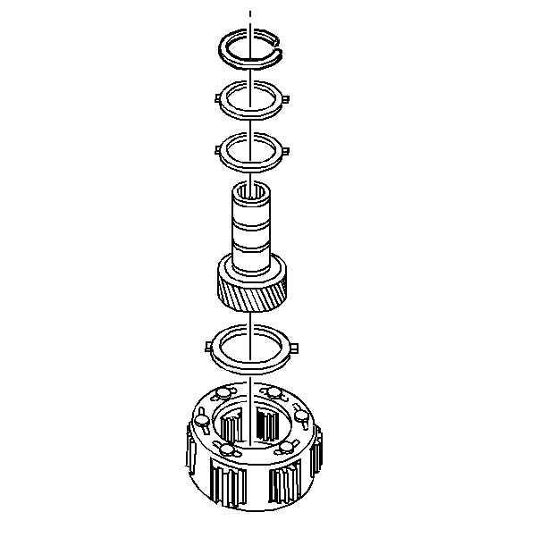
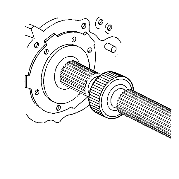
- Use the J 36372 and the J 8092 in order to install the input gear bearing.
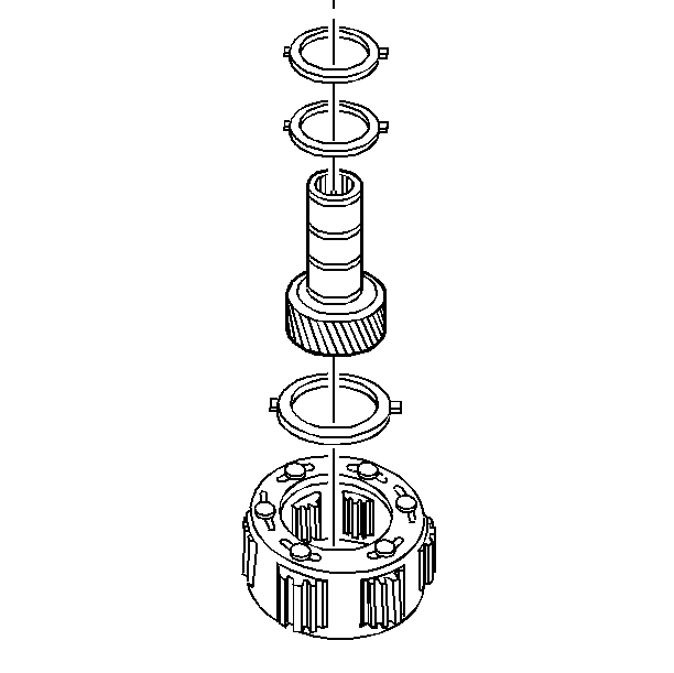
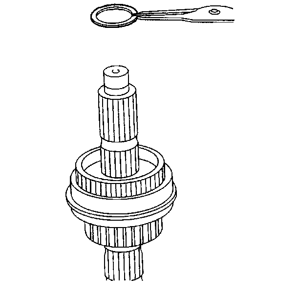
- Install the input gear assembly into the planetary carrier.
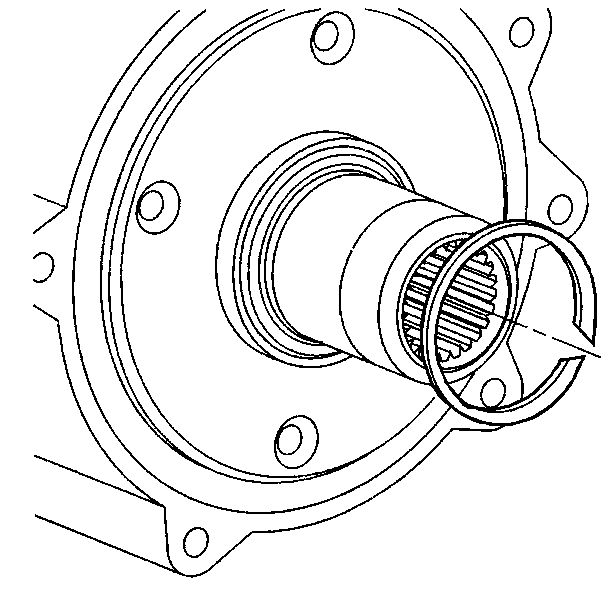
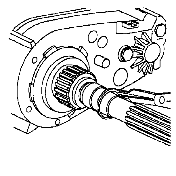
- Install the input gear snap ring.
- Use the J 36372 in order to install the input bearing.
- Use the J 33843 in order to install the mainshaft extension housing seal. Lubricate the seal sealing lips with automatic transmission fluid.
- Use the J 33831 in order to install the input bearing seal into the input bearing retainer. Lubricate the seal sealing lips with automatic transmission fluid.
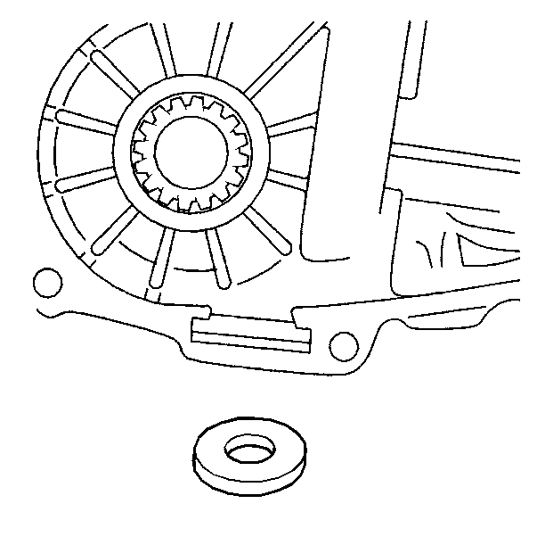
- Install the magnet into the front case half.
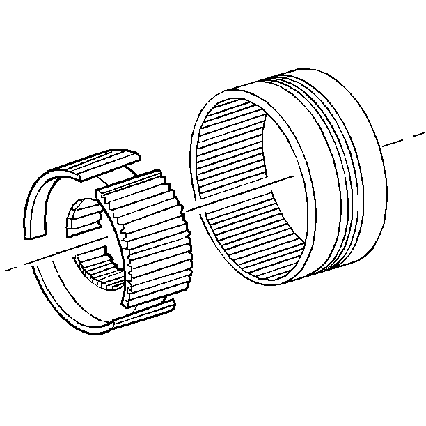
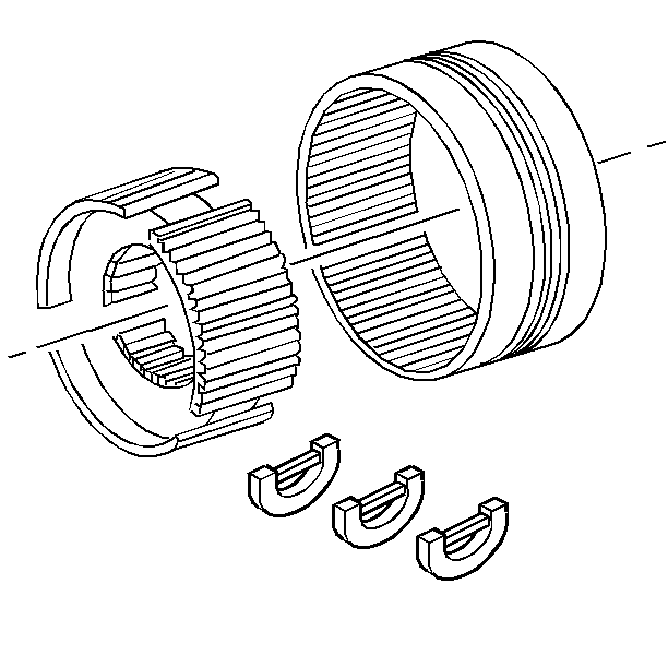
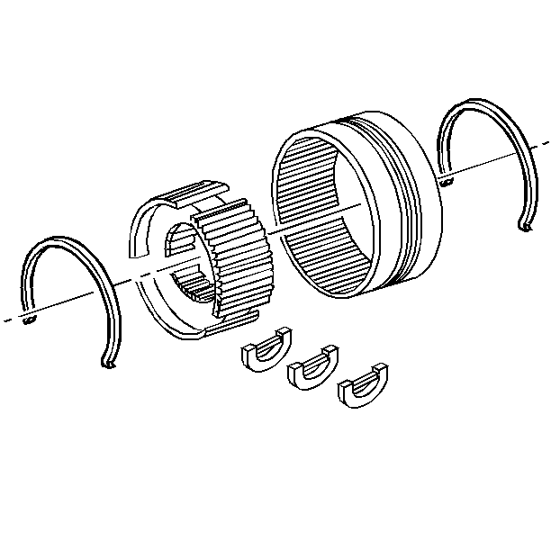
- Install the synchronizer hub to the synchronizer sleeve. Ensure that the marks are aligned.
- Install the synchronizer hub spring retainers.
- Install the synchronizer stop rings.
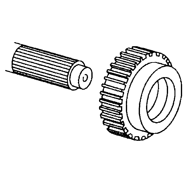
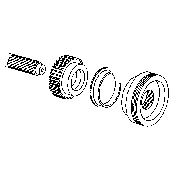
- Install the synchronizer drive sprocket.
- Install the synchronize assembly.
- Install the synchronizer snap ring.
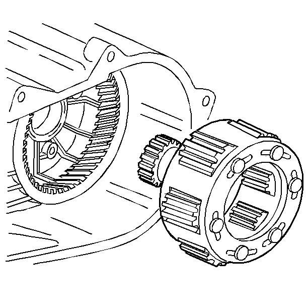
- Use a soft faced hammer in order to install the input and low range gear assembly.
- Install the input gear snap ring.
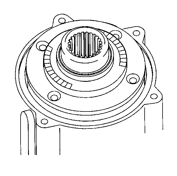
- Install the input bearing retainer. Apply RTV on the bearing retainer mating surfaces.
- Install the input bearing retainer bolts. Apply threadlocker to the bearing retainer bolts.
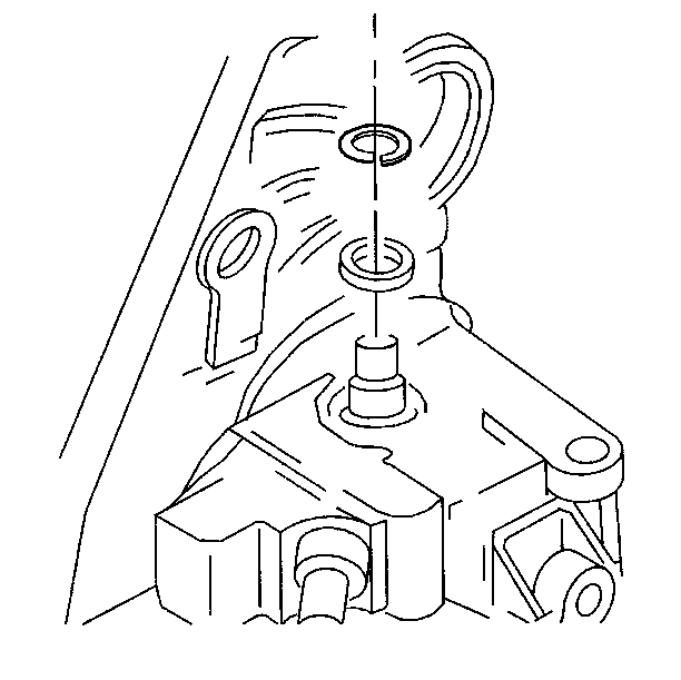
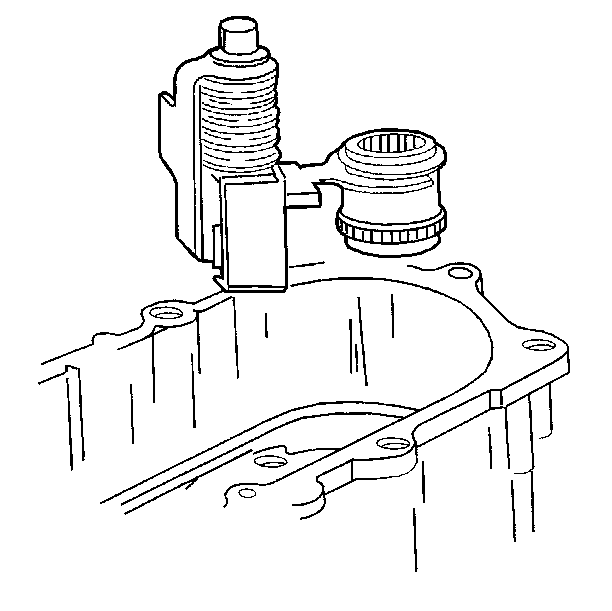
- Install the shift sector assembly.
- Install the sector shaft snap ring.
- Install the range shift hub and fork. Rotate the sector in order to align the range shift fork.
- Install the drive chain, mainshaft, and driven sprocket assembly.
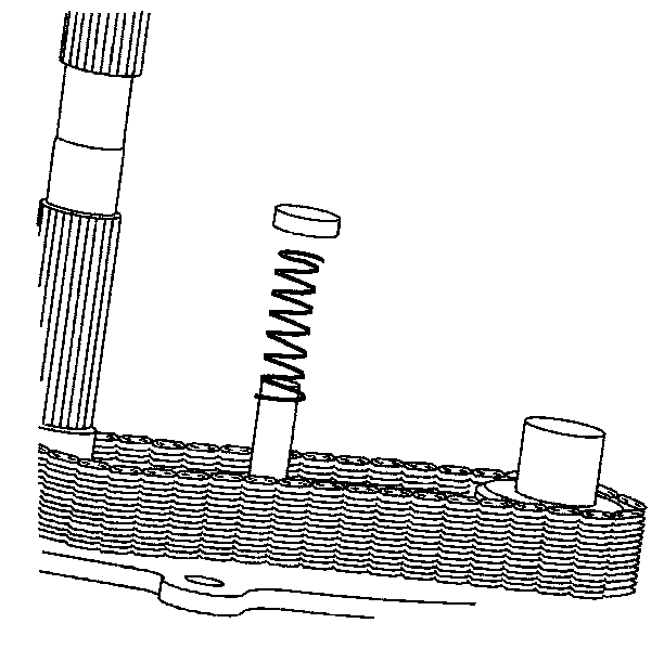
- Install the fork shift spring.
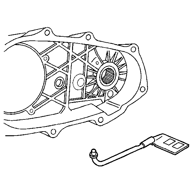
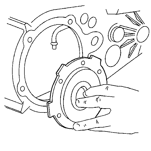
- Install the oil pump pickup tube and screen into the rear case. Pump failure may occur if the O-ring is damaged during installation.
- Install the oil pump onto the pickup tube. Apply RTV sealer to the case mating surfaces.
- Install the rear case to the front case.
- Apply threadlocker to the case bolts. The two longer case bolts and washers go into the doweled case holes.
- Install the case bolts.
- Install the mainshaft snap ring.
- Install the vehicle speed sensor rotor.
- Install the vehicle speed sensor rotor snap ring.
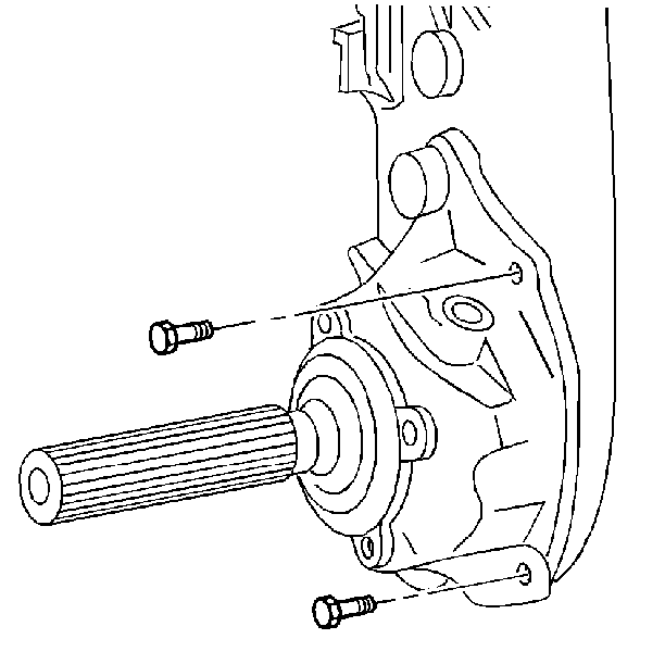
- Install the rear retainer housing. Apply RTV sealer to the rear retainer housing to rear case joint.
- Install the pump retainer housing bolts.
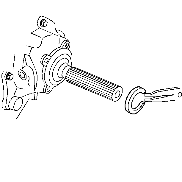
- Install the output bearing snap ring.
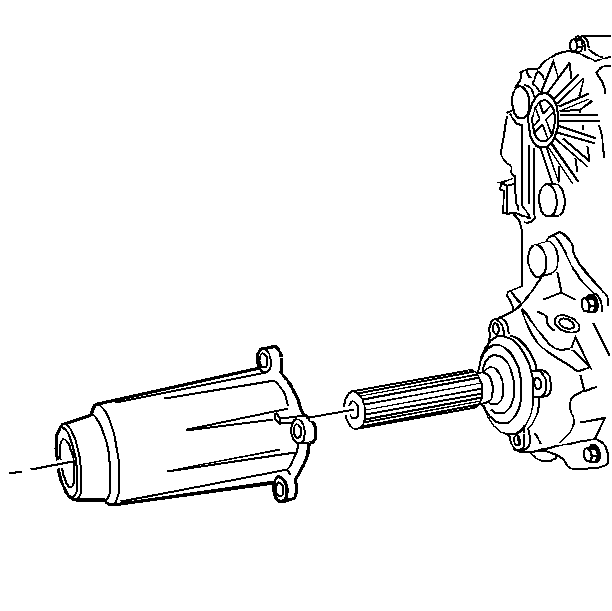
- Apply RTV sealer to the extension housing mating surfaces.
- Install the rear extension housing.
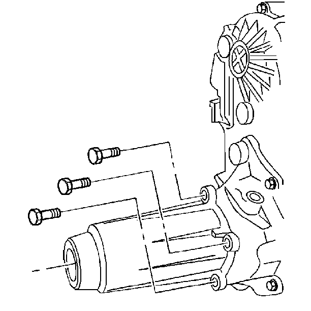
- Apply threadlocker to the rear extension housing bolts.
- Install the rear extension housing bolts.
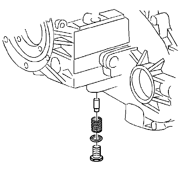
- Install the detent plug, spring, and plunger.
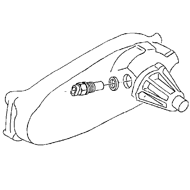
- Install the vehicle speed sensor O-ring to the vehicle speed sensor.
- Install the vehicle speed sensor.
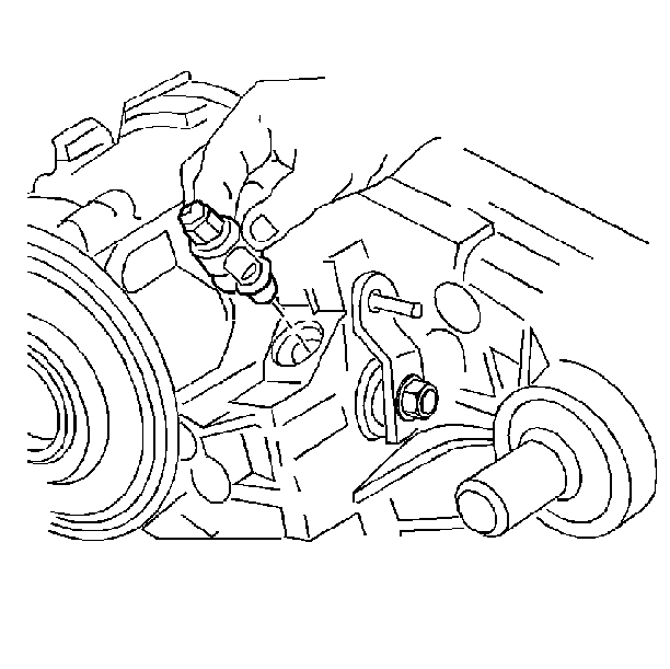
- Install the vacuum switch and its O-ring.
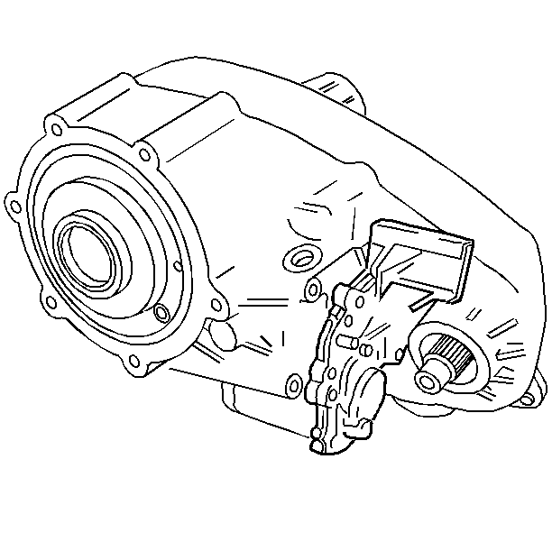
- Install the electronic shift motor.
- Install the electronic shift motor bolts.
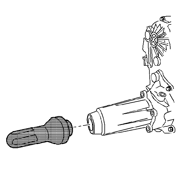
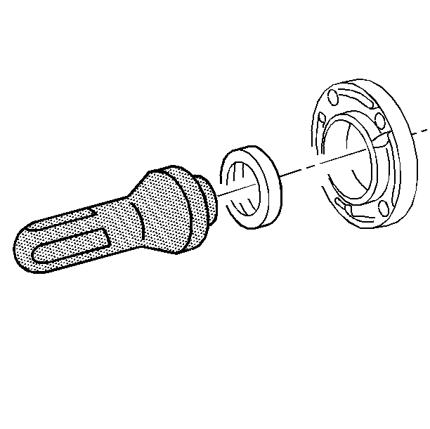
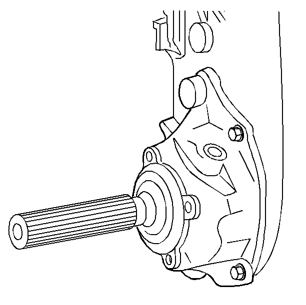
- Use the J 33843 in order to install the front output shaft seal. Lubricate the seal sealing lips with automatic transmission fluid.
- Install the front output shaft snap ring.
Important: Use Dextron® III automatic transmission fluid or the equivalent for lubricant during assembly.
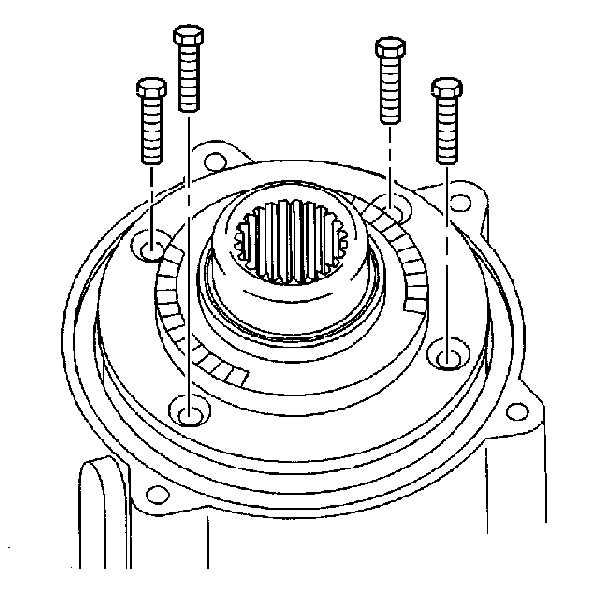
Tighten
Tighten the bolts to 19 N·m (14 lb ft).
Notice: Use the correct fastener in the correct location. Replacement fasteners must be the correct part number for that application. Fasteners requiring replacement or fasteners requiring the use of thread locking compound or sealant are identified in the service procedure. Do not use paints, lubricants, or corrosion inhibitors on fasteners or fastener joint surfaces unless specified. These coatings affect fastener torque and joint clamping force and may damage the fastener. Use the correct tightening sequence and specifications when installing fasteners in order to avoid damage to parts and systems.
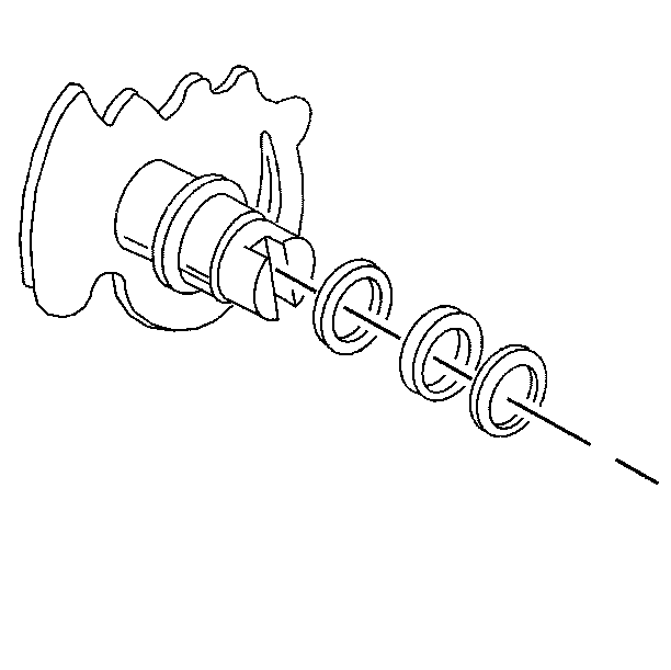
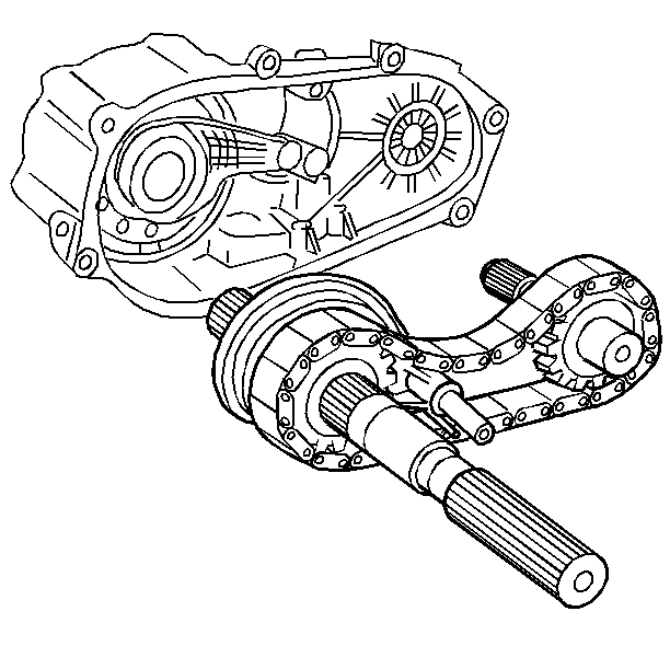
| 25.1. | Install the chain over the mainshaft onto the drive gear. Install the mainshaft assembly, the chain, and the front output shaft as an assembly. |
| 25.2. | Fit the mainshaft assembly, the mode shift fork, and the rail through the range shift fork in the front case half. |
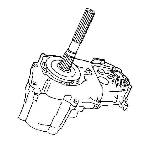
| • | Slide the rear case over the mainshaft onto the front case. |
| • | Be careful not to damage the oil pump. |
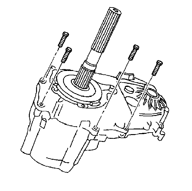
Tighten
Tighten the bolts to 31 N·m (23 lb ft).
Tighten
Tighten the bolts to 41 N·m (30 lb ft).
Tighten
Tighten the bolts to 31 N·m (23 lb ft).
Tighten
Tighten the detent plug to 15 N·m (11 lb ft).
Tighten
Tighten the speed sensor to 31 N·m (23 lb ft).
Tighten
Tighten the vacuum switch to 24 N·m (17 lb ft).
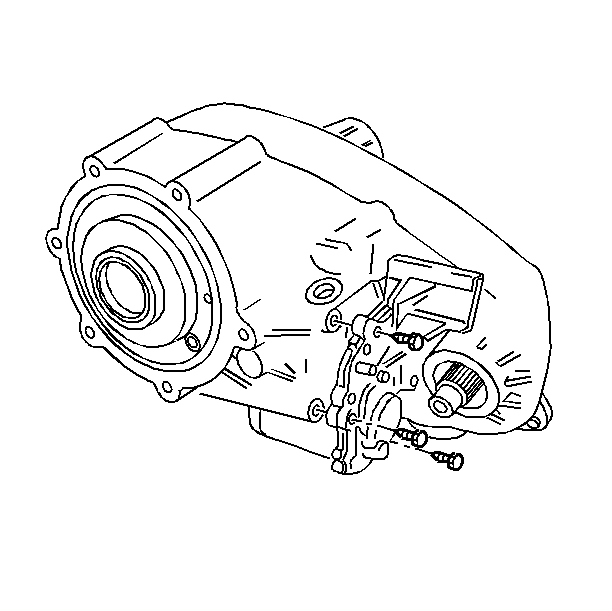
Tighten
Tighten the bolts to 18 N·m (13 lb ft).
