Tools Required
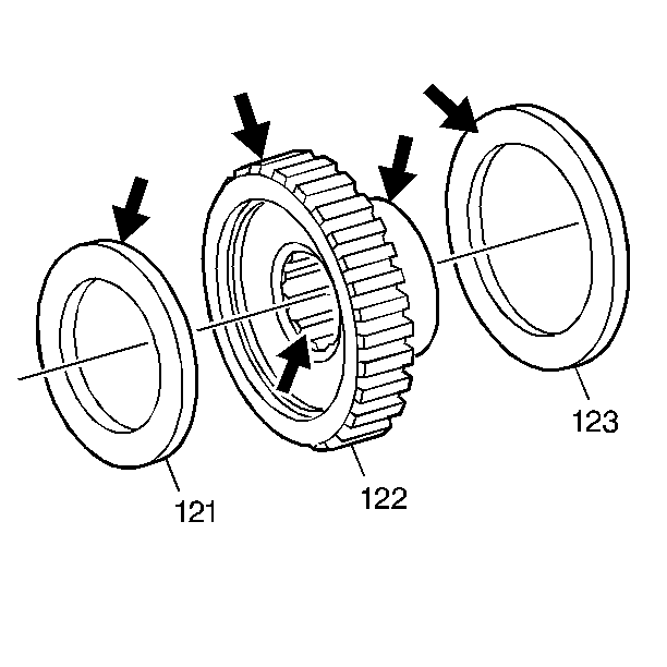
- Inspect the driven sprocket (122) for the
following conditions:
| • | Stripped or damaged splines |
| • | Damaged bearing surfaces |
- Inspect the thrust washer (123) for wear or cracks.
- Inspect the driven sprocket bearing (121) for damage to the races
or to the inner and outer diameters.
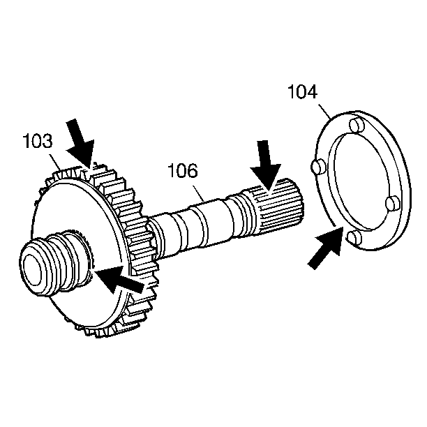
- Inspect the drive sprocket (103) for the
following conditions:
| • | Stripped or damaged splines |
| • | Damaged bearing surfaces |
- Inspect the turbine shaft (106) for the following conditions:
| • | Damaged bushing journal |
| • | Stripped or damaged converter turbine splines |
- Inspect the thrust washer (104) for wear or cracks.
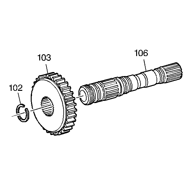
- Install the drive sprocket (103) onto the
turbine shaft (106) and affix the drive sprocket snap ring (102).
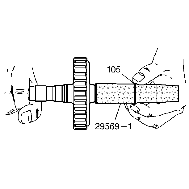
- Install J 29569-1
(as indicated in the illustration) onto the
turbine shaft. Coat the shaft with TRANSJEL™ or equivalent.
- Slide the turbine shaft seals (105) into position one at a time.
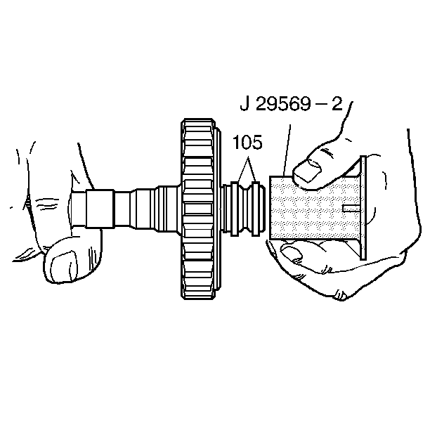
- Use J 29569-2
(as indicated in the illustration) in order to
size the seals (105).
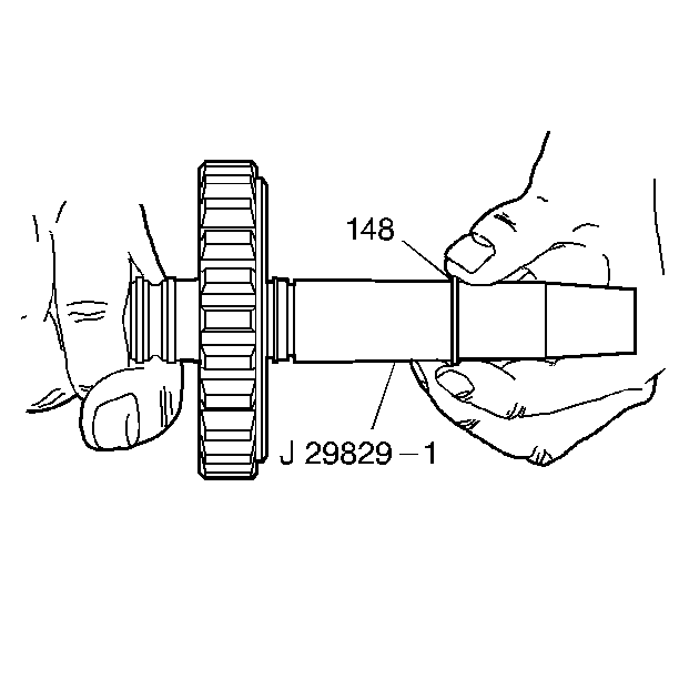
- Use J 29569-1
(as indicated in the illustration) over the
opposite end of the turbine shaft. Coat the shaft with TRANSJEL™ or
equivalent.
- Slide the turbine shaft oil seal ring (148) into position.
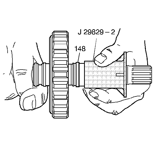
- Use J 29569-2
(as indicated in the illustration) in order to
size the seal (148).


