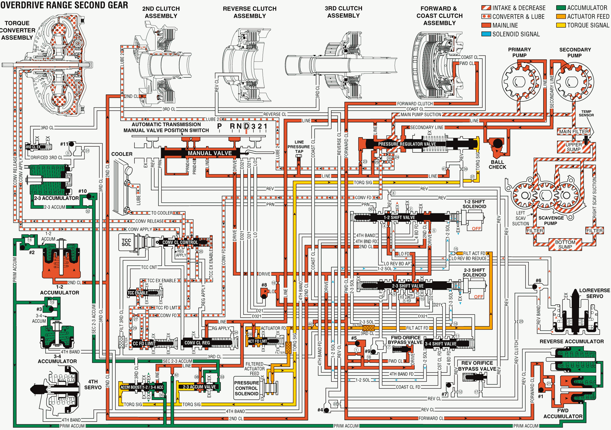
As the speed of the vehicle increases, the Powertrain Control Module (PCM) receives input signals from various engine and transmission sensors. The PCM uses this data to de-energize the 1-2 shift solenoid (SS) valve in order to shift the transmission into second gear at the appropriate time.
Second Clutch Applies
1-2 Shift Solenoid (SS) Valve
De-energized (turned OFF) by the PCM, the 1-2 SS valve exhausts fluid through the solenoid valve. This creates a low fluid pressure from the 1-2 SS valve in the circuit. This low solenoid pressure allows the 1-2 shift valve to move to the upshifted position. The 3-4 shift valve moves to the downshifted position.
1-2 Shift Valve
Spring force and low fluid pressure in the 2-3 shift solenoid (SS) valve hold the 1-2 shift valve in the upshifted position. The 1-2 shift valve allows orificed drive fluid to pass through the valve into the second clutch circuit. Second clutch fluid is then routed to the 1-2 accumulator piston and to the second clutch piston in order to apply the clutch.
1-2 Shift Accumulation
1-2 Accumulator Piston
Second clutch fluid actuates the 1-2 accumulator piston. The fluid then forces the piston to move against spring force and 1-2 accumulator fluid on the opposite side of the piston. 1-2 accumulator fluid is then forced back through its circuit to checkball #2.
#2 Checkball (Primary Accumulator and 1-2 Accumulator)
The #2 checkball is located in the accumulator housing. The checkball is unseated by 1-2 accumulator fluid. This allows the fluid to enter the primary accumulator circuit. Primary accumulator fluid is then routed to the 1-2 & 3-4 accumulator valve.
1-2 & 3-4 Accumulator Valve
The 1-2 & 3-4 accumulator valve is biased by torque signal pressure and by orificed primary accumulator fluid. The valve regulates the exhaust rate of the 1-2 accumulator fluid during a 1-2 shift.
Low & Reverse Releases
Low & Reverse Servo
When the 1-2 shift valve is held in the upshifted position, an exhaust port is opened. Fluid in the Low & Reverse band reduce circuit exhausts at the valve while spring force, acting on the piston, forces the servo downward. The downward movement of the servo enables the release of the Low & Reverse band.
#6 Checkball (Low & Reverse Band Apply, Reduce)
The #6 checkball is positioned against the Low & Reverse band apply circuit. The checkball allows Reverse band fluid from the Low & Reverse servo piston to enter the Low & Reverse band reduce circuit. Fluid in the Low & Reverse band reduce circuit is then routed to the 1-2 shift valve where the fluid exhausts.
Overdrive Range, Second Gear

