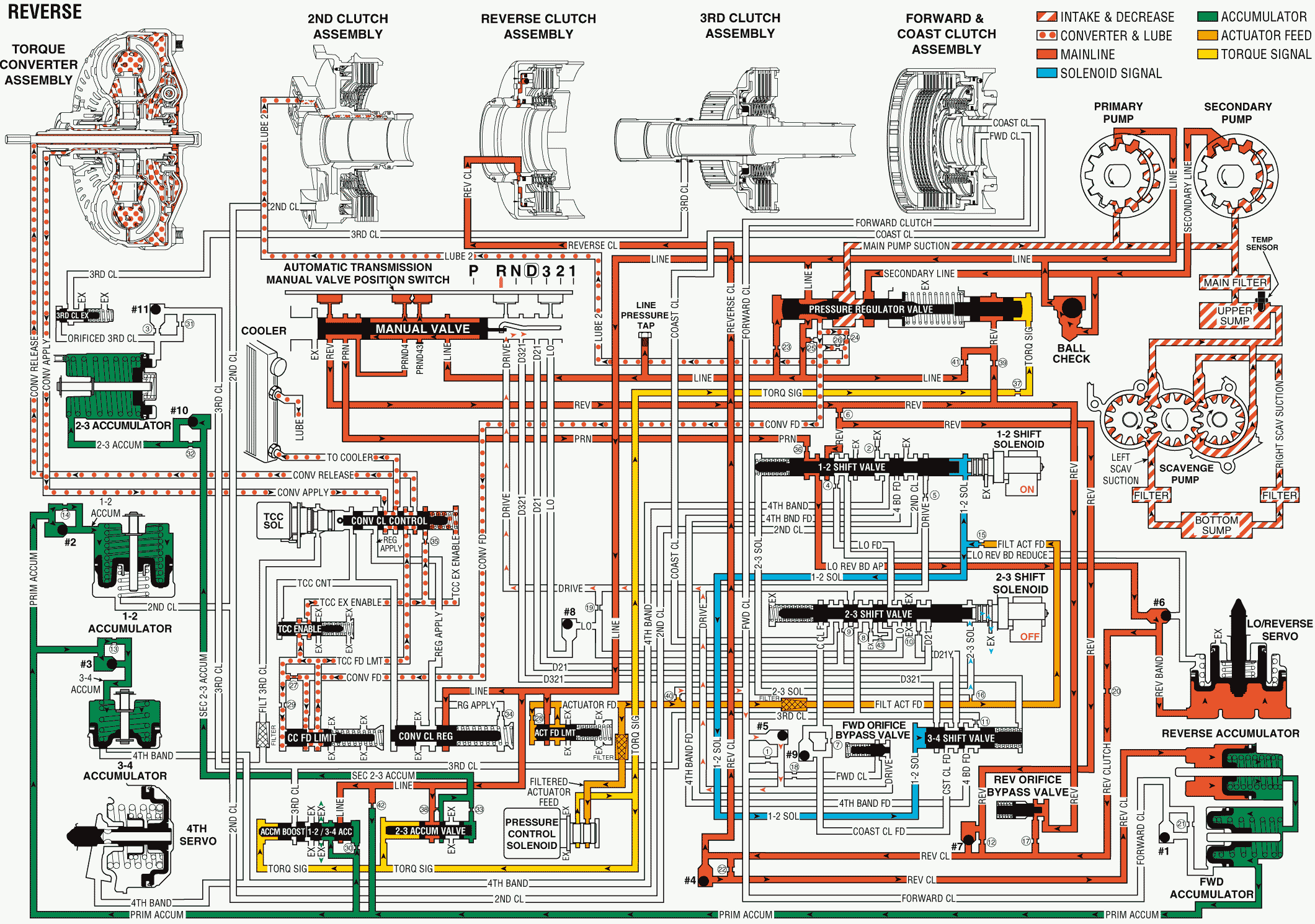
When the gear selector lever moves to the Reverse (R) position, the following changes occur to the hydraulic and electrical systems inside the transmission:
Pressure Regulation
Manual Valve
The gear selector lever mechanically moves the manual valve. While this is occurring, the valve directs line pressure through the PRND4 fluid passage into the reverse circuit. Reverse fluid then routes to the pressure regulator valve and to the reverse orifice bypass valve. Reverse fluid then passes through orifice #6. The fluid seats checkball #7 before routing to the 1-2 shift valve.
Automatic Transmission Manual Valve Position Switch
Line fluid pressure activates the reverse, PRND4 and the PRND43 pressure switches to complete their circuits. The sequence of open and closed switches provides the input data to the PCM indicating the manual valve position.
Pressure Regulator Valve
Reverse fluid pressure combines with torque signal fluid to increase hydraulic pressure in the line circuit. A change to the vehicle operating conditions produces changes in the throttle position. The changes to the throttle position influence fluctuations in line pressure.
Reverse Clutch Applies
Reverse Orifice (Bypass) Valve
Spring force holds the bypass valve closed. The valve opens under high pressure and routes reverse fluid through orifice #17 into the reverse clutch circuit. This valve provides an additional feed into the reverse clutch circuit in order to quickly apply and hold the reverse clutch.
The #7 Checkball (Reverse/Reverse Clutch)
The #7 checkball is located in the valve body. The checkball is seated against the spacer plate in order to force reverse fluid through orifice #12 before the fluid enters the reverse clutch circuit.
The 1-2 Shift Valve
This valve operates in the downshifted position. The valve allows orificed PRN fluid to enter the Low & Reverse band apply fluid passage. Low & Reverse band apply fluid is then routed to checkball #6.
The #6 Checkball (Low/Reverse Band Apply/Reduce)
The #6 checkball is located in the valve body. The checkball is seated against the Low & Reverse band reduce passage. The checkball routes fluid into the Low & Reverse band apply circuit. Low & Reverse band apply is then routed to the Low & Reverse servo piston and actuates the piston.
The #4 Checkball (Reverse Clutch)
The #4 checkball is located in the accumulator housing. The checkball is unseated by reverse clutch fluid, allowing reverse clutch pressure to actuate the reverse accumulator piston.
Reverse Accumulator Assembly
Primary accumulator fluid on the spring side of the reverse accumulator piston is forced back through its circuit to the 1-2 & 3-4 accumulator valve. The 1-2 & 3-4 accumulator valve then regulates the exhaust of primary accumulator fluid.
Torque Converter Cooler & Lube
Pressure Regulator Valve
Line pressure at the valve forces fluid through the converter feed circuit which then routes the fluid to the converter clutch feed limit valve. Fluid passes through the valve and enters the TCC feed limit circuit. The limited fluid amount is then routed through orifice #29 and enters the orificed feed limit passage. The limited fluid amount is also routed to the TCC enable valve and to the converter clutch control valve.
TCC Enable Valve
Spring force holds the TCC enable valve in the downshifted position. This allows a limited fluid amount to pass through the valve and enter the orificed TCC exhaust enable circuit. Orificed TCC exhaust enable fluid then routes to the converter clutch control valve.
Converter Clutch Control Valve
Spring force holds the Converter Clutch Control valve in the downshifted position. Orificed TCC exhaust enable fluid routes to the spring end of the valve and through orifice #35, where the fluid enters the TCC exhaust enable circuit. At the same time, a limited fluid amount routes through the valve and enters the converter release circuit.
Torque Converter
Converter release fluid routes to the cover side of the TCC pressure plate, keeping the pressure plate in the released position. The fluid which is released from the converter passes around the plate and enters the converter apply circuit. This routes the fluid back to the converter clutch control valve.
Converter Clutch Control Valve
Converter apply fluid routes through the valve, through the transmission cooler, and into the lube circuits through the transmission.
Reverse

