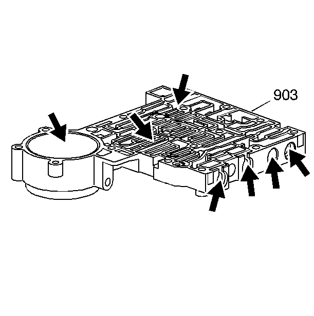
- Inspect the lower control
valve body (903) for scratches or debris in the valve bores.
- Inspect the mating surfaces for damage.
- Inspect the servo bore for damage.
- Inspect all fluid passages for debris.
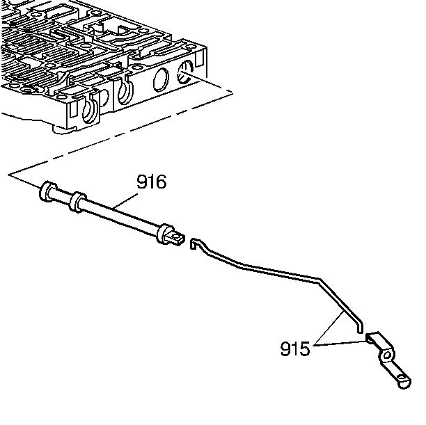
- Attach the manual valve
link and clip (915) to the manual valve (916). Install the manual valve and
link into the lower control valve body.
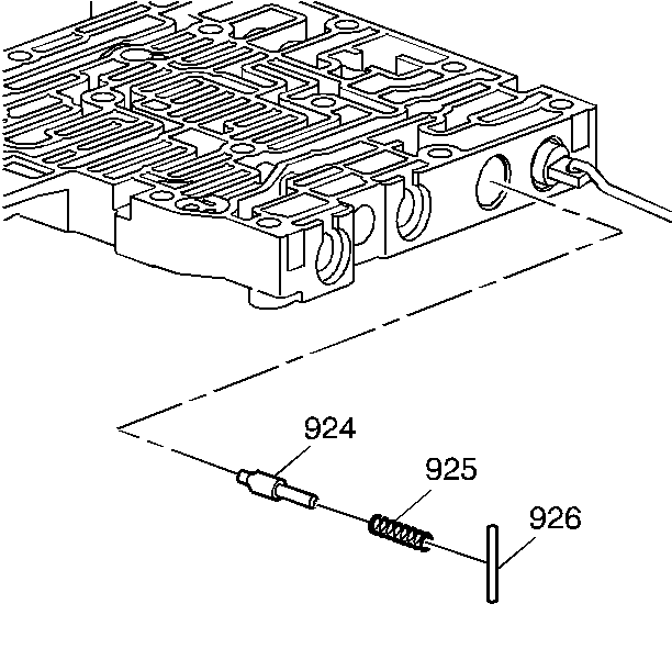
- Install the following
parts:
| • | The forward orifice bypass valve (924) |
| • | The forward orifice bypass valve spring (925) |
| • | The coiled spring flag pin (926) |
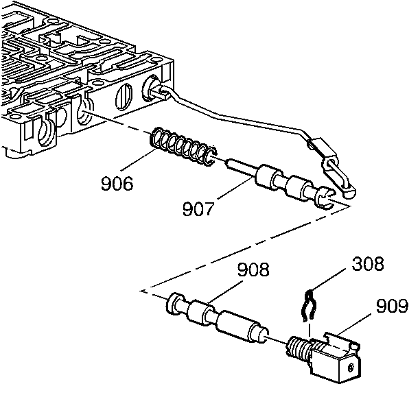
- Install the following
parts:
| • | The 2-3 shift valve spring (906) |
| • | The 2-3 C shift valve (907) |
| • | The 2-3 D shift valve (908) |
| • | The 2-3 shift solenoid valve (909) |
| • | The 2-3 shift solenoid valve retainer clip (308) |
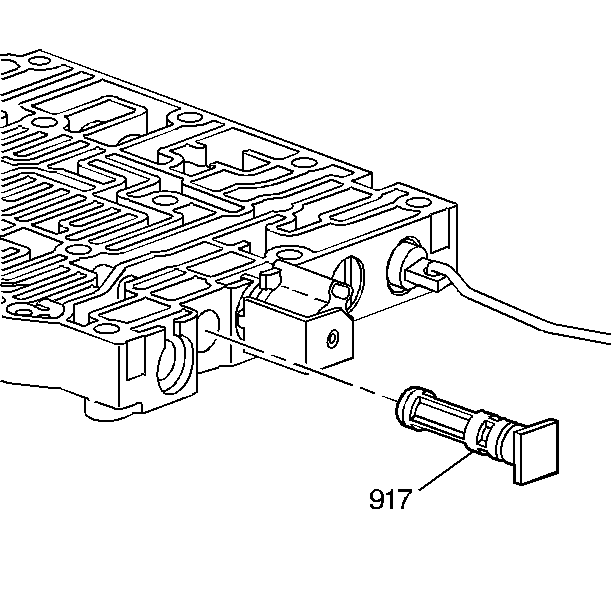
- Install the solenoid screen
assembly (917).
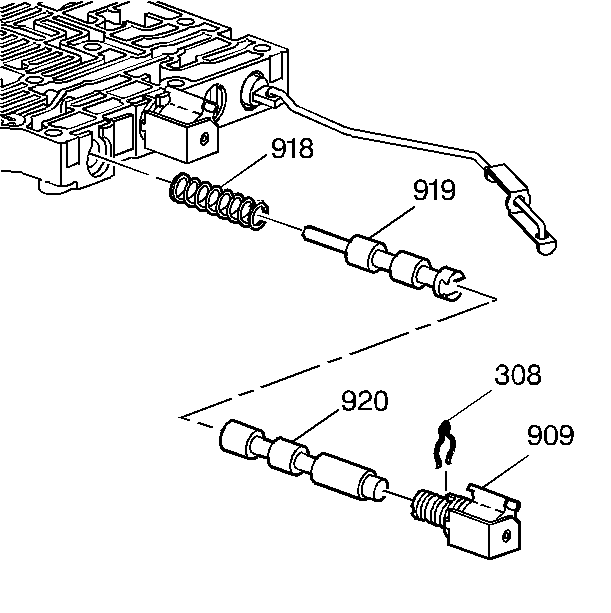
- Install the following
parts:
| • | The 1-2 shift valve spring (918) |
| • | The 1-2 A shift valve (919) |
| • | The 1-2 B shift valve (920) |
| • | The 1-2 shift solenoid valve (909) |
| • | The 1-2 shift solenoid valve retainer clip (308) |
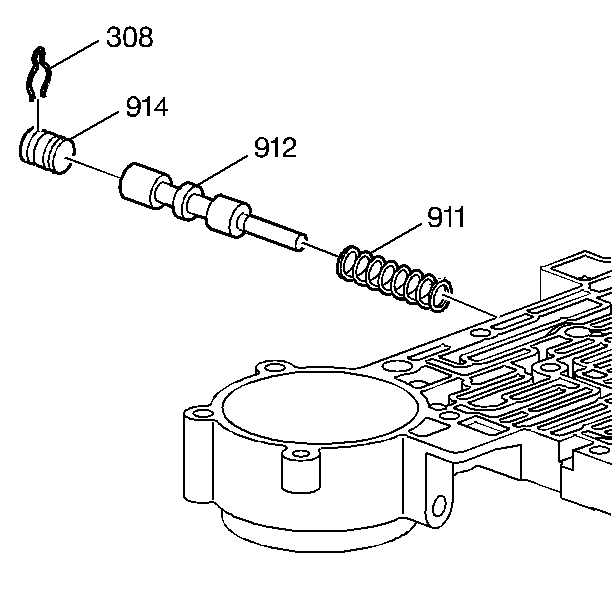
- Install the following
parts:
| • | The 3-4 shift valve spring (911) |
| • | The 3-4 shift valve (912) |
| • | The bore plug retainer clip (308) |
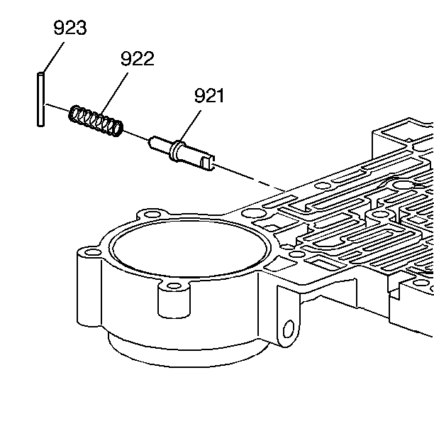
- Install the following
parts:
| • | The reverse orifice bypass valve (921) |
| • | The reverse orifice bypass valve spring (922) |
| • | The coiled spring flag pin (923) |
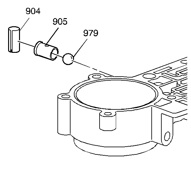
- Install the following
parts:
| • | The ball check capsule (905) |
| • | The spring retainer (904) |
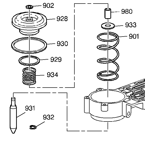
- Install the washer (933)
and the sleeve (980) onto the servo pin (931).
- Install the servo cushion spring (934) in the servo piston (928).
- Then install the pin (931) into the piston and install the retaining
ring (902) onto the servo pin.
- Place the return spring (901) into the servo bore.
- Place new seals (929, 930) on the servo piston (929), and install
the piston and pin assembly into the servo bore. Attach the retaining ring
(932) to the pin.
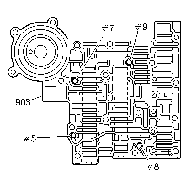
- Install the checkballs
(5, 7, 8, 9) into the lower control valve body (903). Retain the checkballs
in position with Transjel™.


