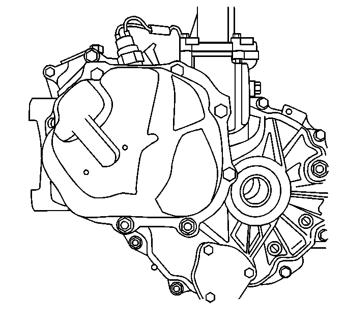
Notice: If the transaxle side cover is frozen to the left case, tap around the
side cover with a rubber mallet until the side cover is free of the left case.
DO NOT attempt to pry the side cover away from the left case with metal tools
or damage to the left case and side cover mating surfaces could result.
- Remove the 6 bolts and 2 nuts/washers. Remove the transaxle
side cover from the left case.
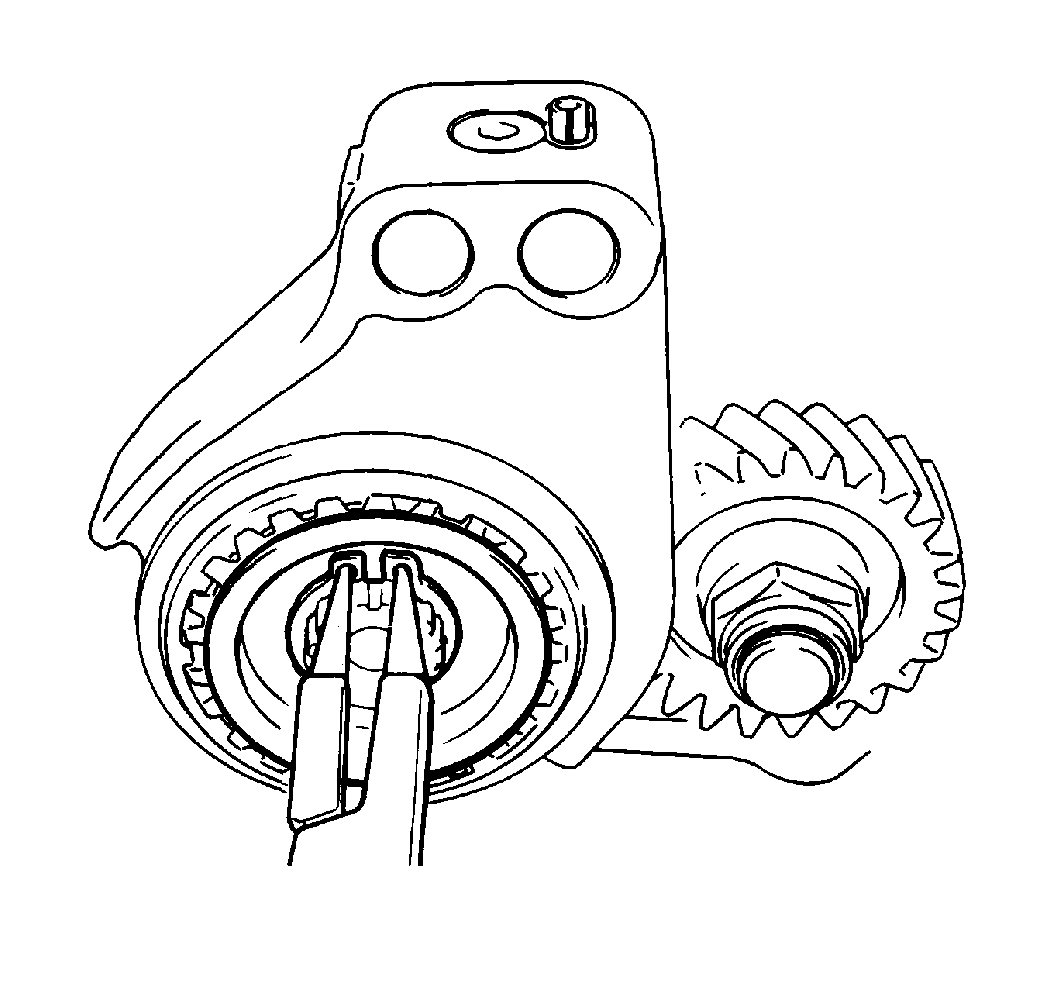
- Remove the following components
from the input shaft:
| 2.1. | The fifth speed synchronizer retainer |
| 2.2. | The fifth speed synchronizer hub plate |
- Engage the transaxle by pushing in on the gearshift shaft.
- Engage the fifth gear by sliding the fifth speed sleeve down.
The transaxle is now locked in two gears, preventing input shaft rotation
and permitting countershaft nut removal.
- Use a center punch and a hammer in order to unstake the countershaft
nut.
- Remove the countershaft nut from the countershaft.
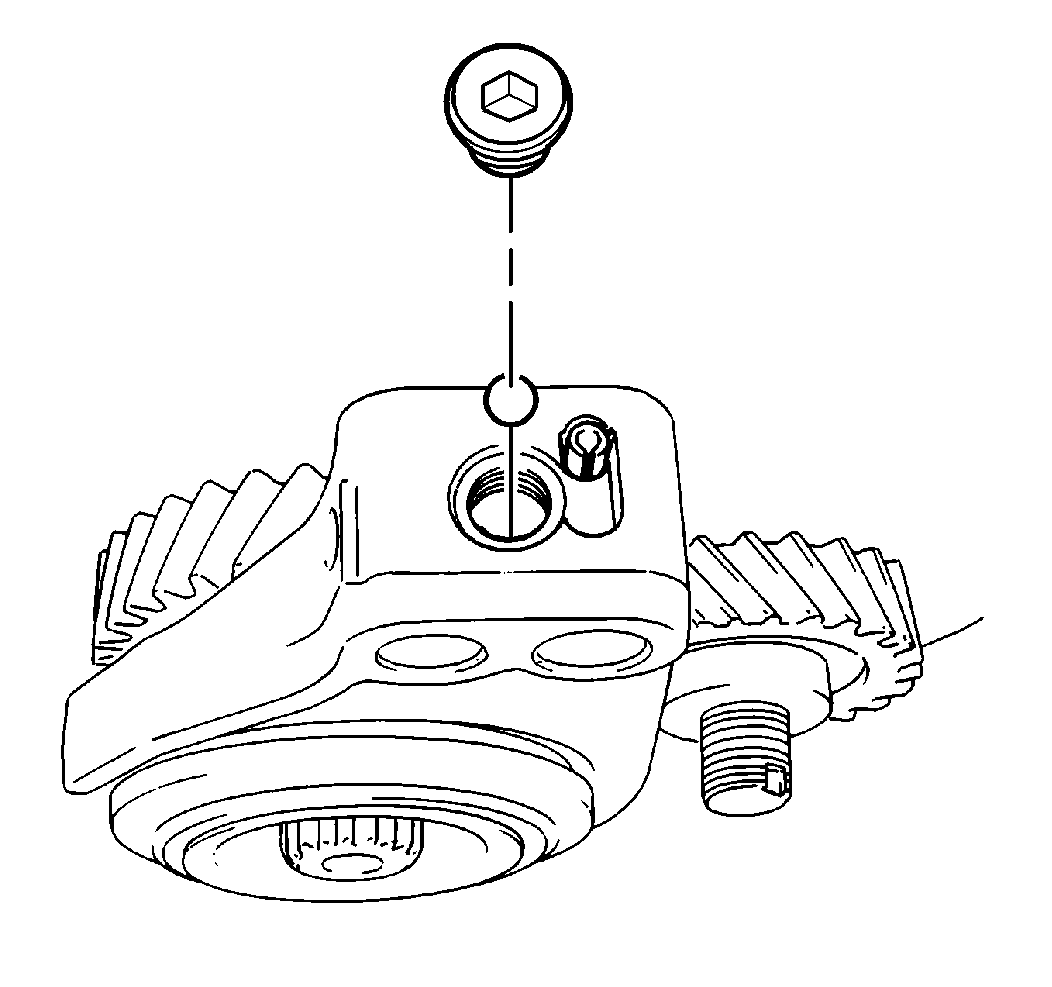
Important: Use a magnet in order to help remove the guide ball from the fifth speed
gearshift fork.
- Remove the gearshift fork plug and the guide ball from the fifth speed
gearshift fork.
- Move the transaxle gearshift shaft to the neutral position.
- Use a standard drift punch and a hammer in order to remove the
gearshift fork roll pin.
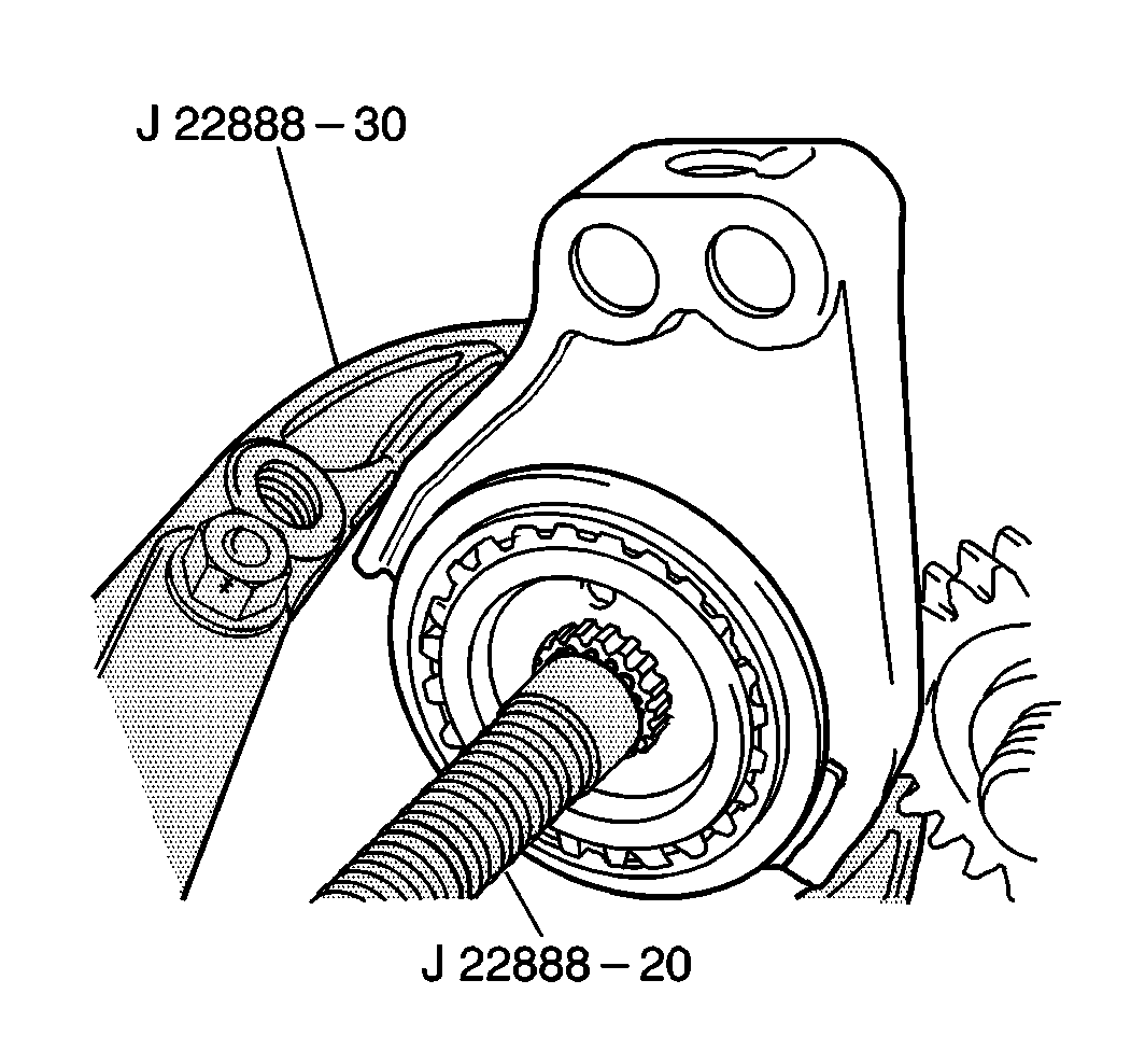
- Using your hands, remove
the following components from the input shaft (if you cannot remove the assembly
manually, use J 22888-20A
with two J 22888-30
):
| • | The fifth speed gearshift fork |
| • | The fifth speed sleeve and hub |
| • | The synchronizer ring spring |
| • | The high speed synchronizer ring spring |
| • | The fifth speed synchronizer ring |
| • | The input shaft fifth gear |
- Remove the fifth speed gearshift fork from the fifth speed sleeve
and hub assembly.
- Remove the synchronizer ring spring and the fifth speed hub from
the fifth speed sleeve.
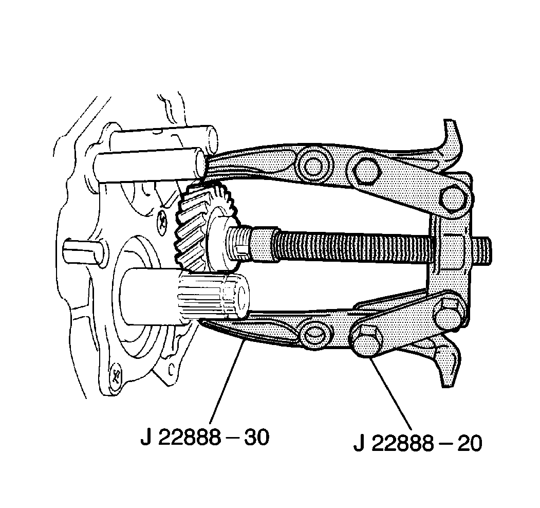
- Using your hands, remove
the countershaft fifth gear from the countershaft (if you cannot remove the
gear manually, use J 22888-20A
with J 22888-30
.
Important: If the screws are damaged during removal, replace with new screws.
- Remove the following components from the left case in order:
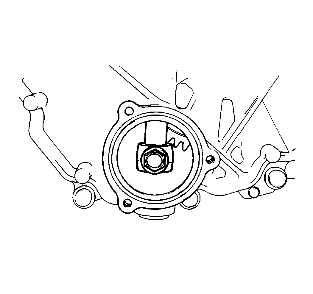
- Remove the gearshift yoke
bolt from the gearshift yoke.
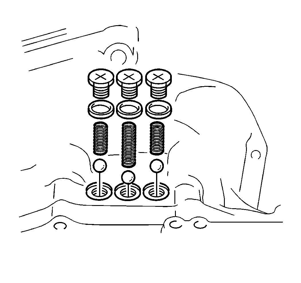
Important: The locating springs are of various sizes for ease of assembly. Remember
the location and position of each spring in order to ensure correct installation.
- Remove the following components from the right case:
| • | The gearshift shaft screws with the washers |
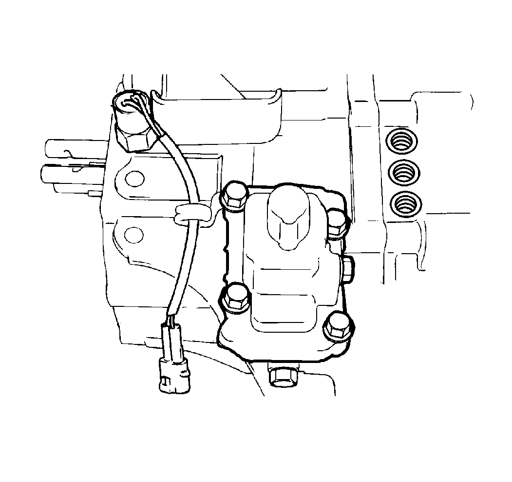
Important: Do NOT remove the fifth-to-reverse interlock bolt for removal of the
gearshift guide case.
- Remove the following components from the left case:
| 17.2. | The harness bracket |
| 17.3. | The gearshift guide case |
| 17.4. | The backup lamp switch with O-ring |
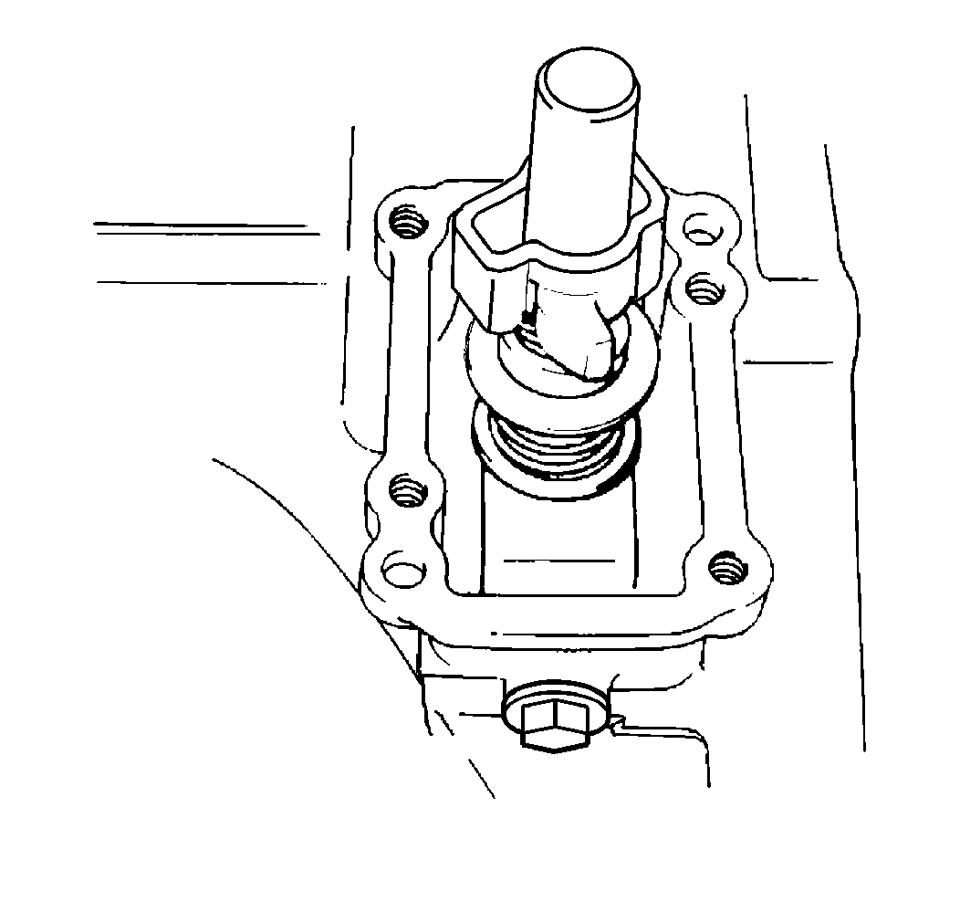
- Remove the gearshift interlock
bolt and the washer from the left case.
- Remove the gearshift and select shaft assembly from the left case.
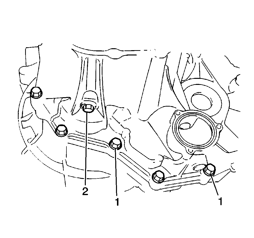
- Remove the reverse idler
shaft bolt (2) and the washer from the left case.
- Remove the eleven case bolts (1) from the left case.
- Remove the two case bolts from inside of the right case.
Important: Separate the transaxle cases with the right case (clutch housing) facing
downward so that all of the internal components remain in the right case.
- Remove the left case from the right case by lifting the left case up
and off of the right case.
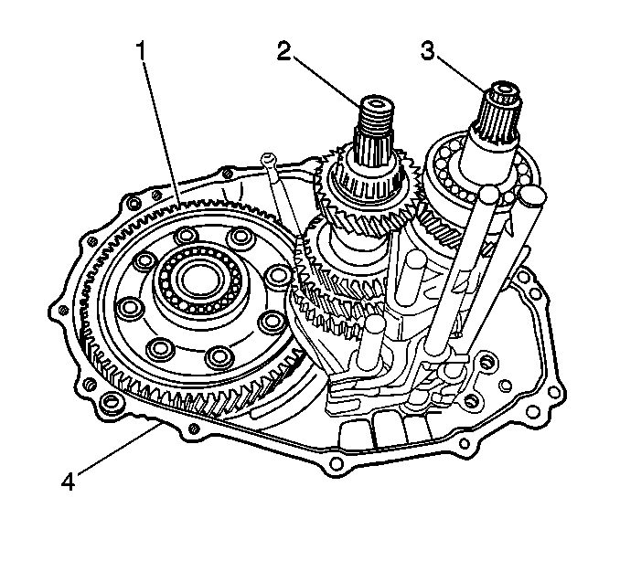
- Remove the gearshift yoke
from the gearshift arm.
- Remove the following components from the right case (4):
| • | Reverse idler gear shaft with the washer |
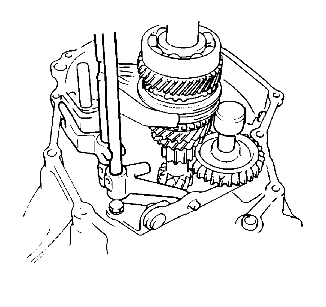
- Remove the reverse idler
lever bolts and assembly.
Important: When removing the 5th and reverse gearshift shaft and guide shaft, push
the high speed gearshift shaft in. Shift the high speed gearshift shaft to
4th gear in order to remove the 5th and reverse gearshift shaft and guide
shaft.
- Remove the following components simultaneously from the right case:
| • | The fifth and reverse gearshift guide shaft |
| • | The fifth and reverse gearshift shaft |
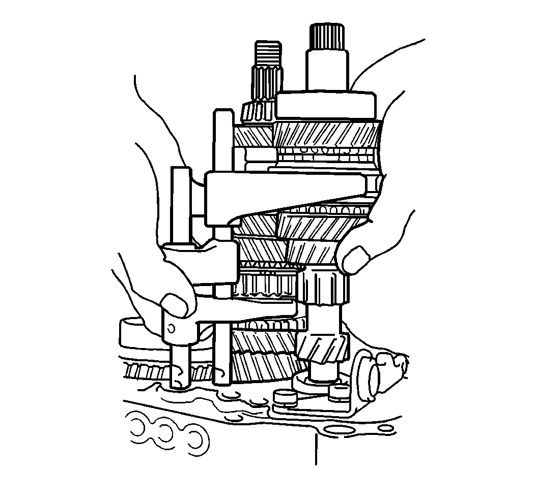
- Tap the input end of the
assembly with a plastic mallet.
- Remove the following components simultaneously as a cluster:
| • | The input shaft assembly |
| • | The countershaft assembly |
| • | The high speed and low speed gearshift shafts |
- Remove the following components from the input shaft and countershaft
assemblies:
| • | The high speed gearshift shaft |
| • | The low speed gearshift shaft |
- Separate the input shaft assembly from the countershaft assembly.
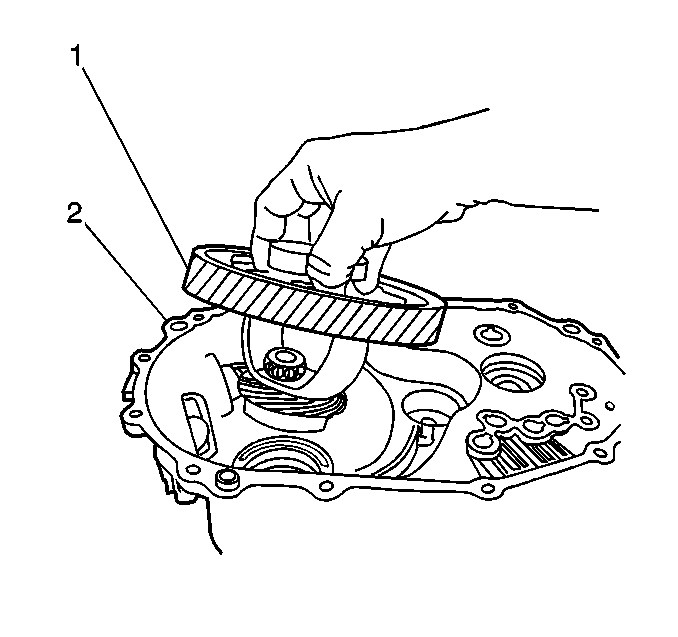
- Remove the differential
assembly from the right case.
| • | Grasp the differential assembly (1). |
| • | Lift the differential assembly up and out of the right case (2). |


