Tools Required
J 35539 Output Shaft Remover and Installer
- Inspect the output shaft seal ring for cuts or damage. Replace as necessary.
- Move the manual shift lever to any position other than Park.
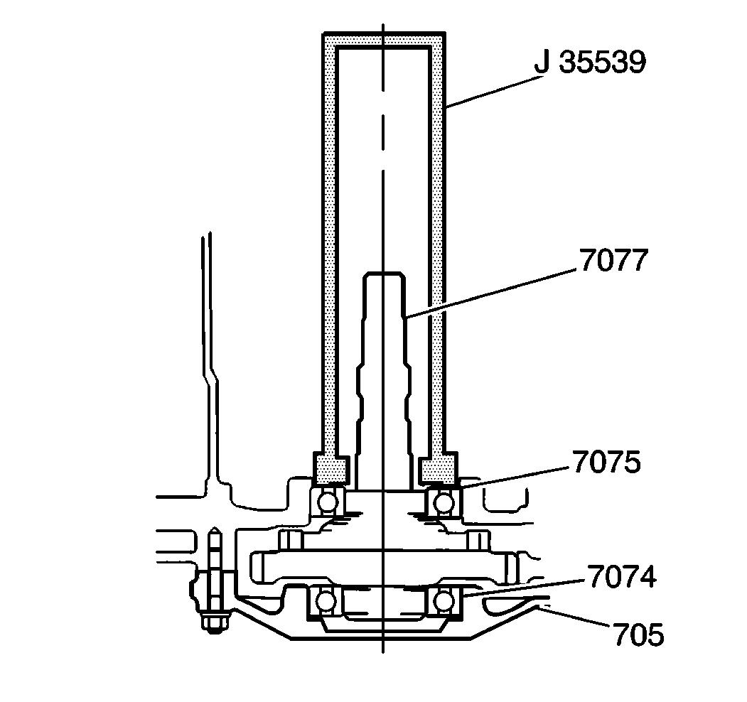
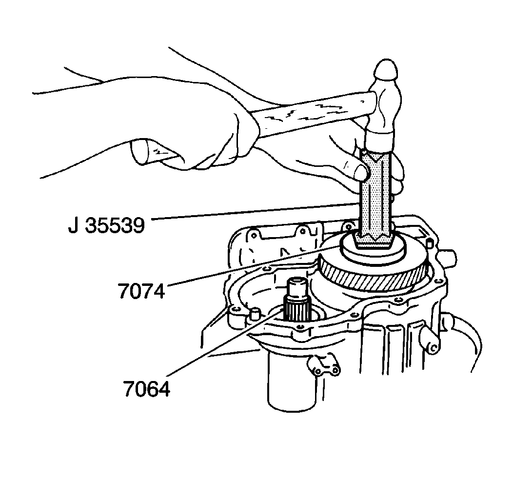
- Install the output shaft assembly into the transaxle case. Using a J 35539 , tap on the output shaft bearing (7074). Excessive hammering will damage the transaxle case.
- Move the manual shift lever into the Park position in order to lock the output shaft in place.
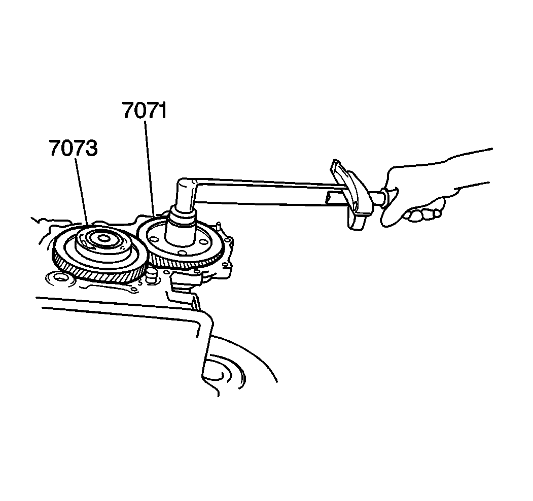
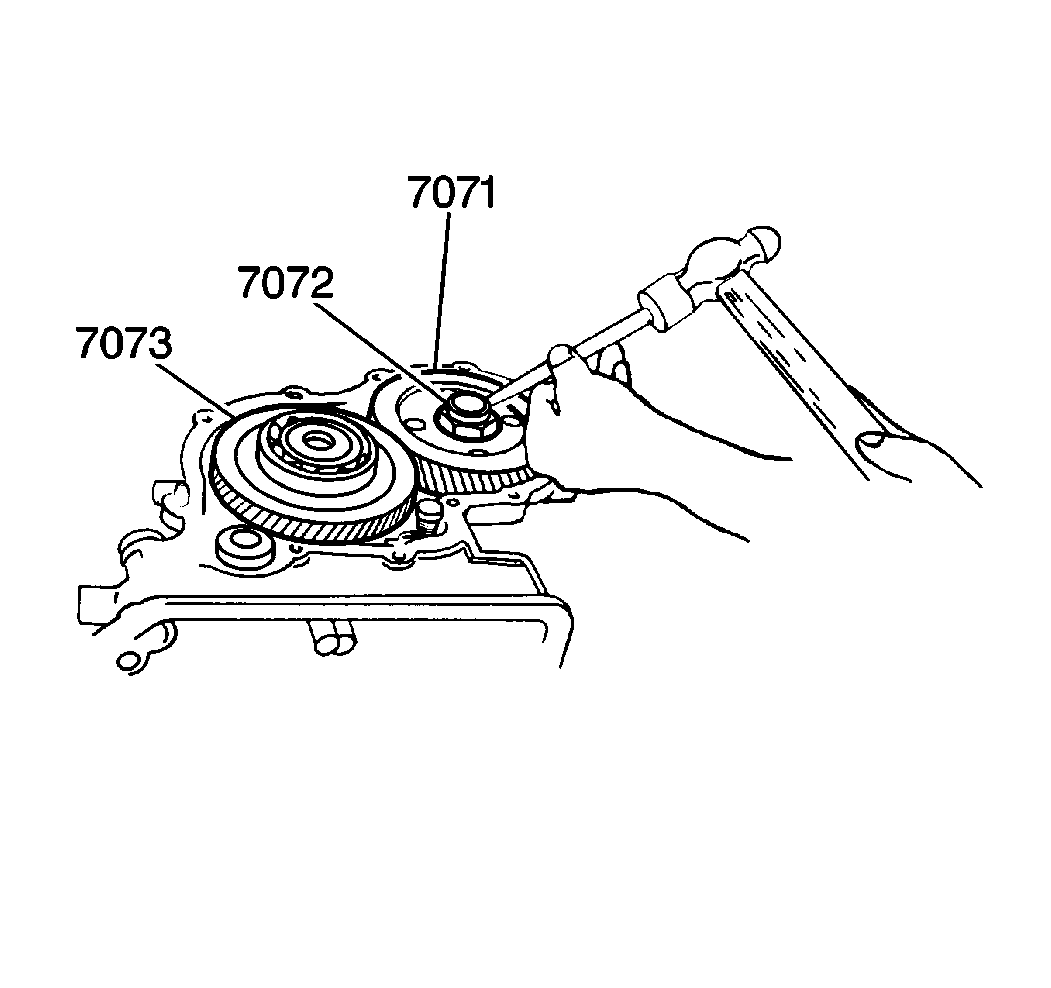
- Install the reduction driven gear (7071). Confirm that the reduction driven gear meshes with the reduction drive gear (7073).
- Install the reduction driven gear nut.
- Using a hammer and chisel, stake the reduction driven gear nut (7072) in two places.
- Inspect the output shaft and the countershaft for smooth operation by rotating both the reduction drive gear (7073) and the reduction driven gear (7071) by hand.
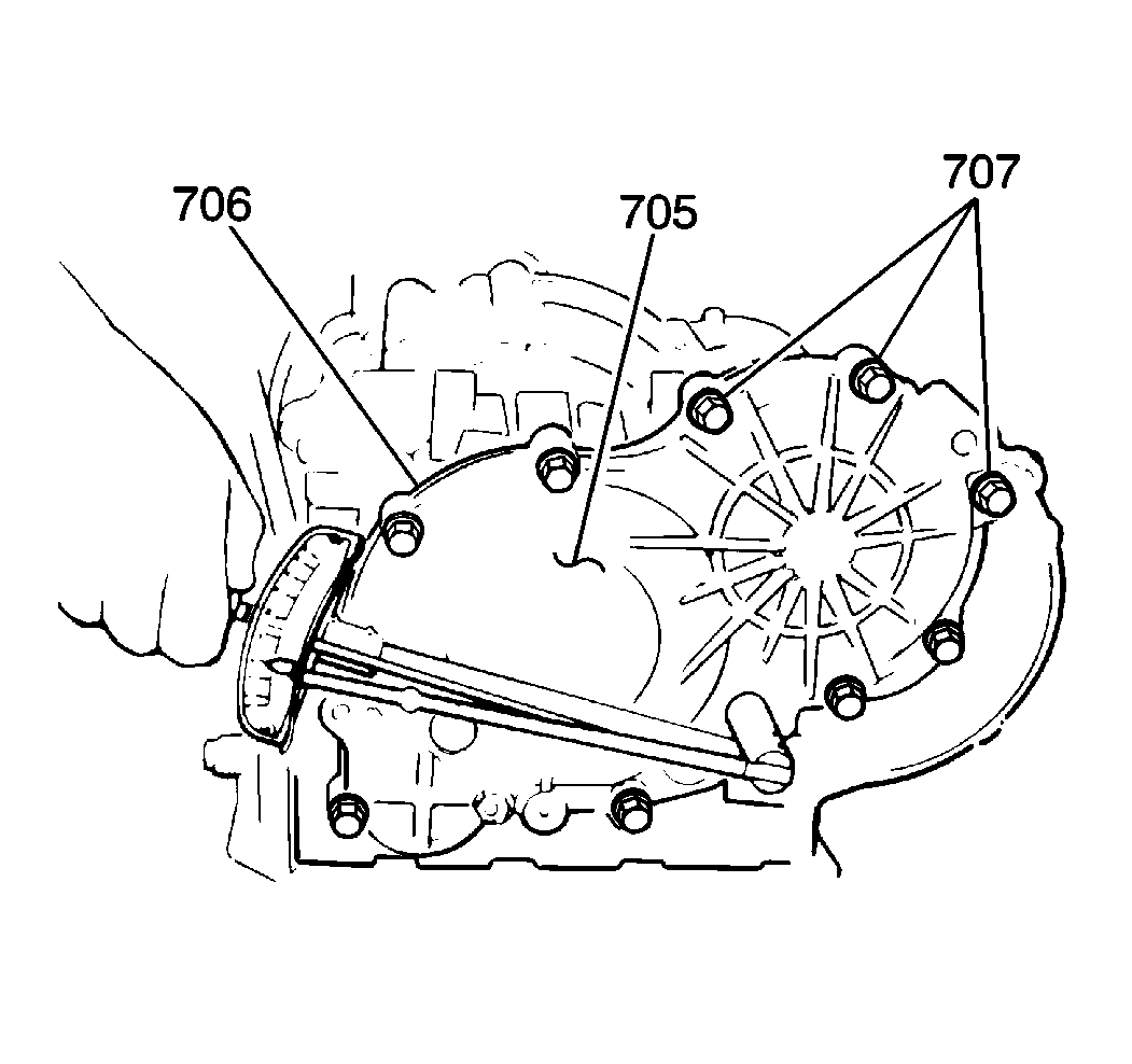
- Install a new rear case cover gasket (706).
- Install the rear case cover (705). Confirm that the output shaft bearing on the reduction drive gear enters the rear case cover bore smoothly.
- Install five of the cover bolts (707). The remaining five bolt positions are currently concealed by the J 35525-A . You must install these bolts in a later procedure.
- Install two rear case cover nuts.
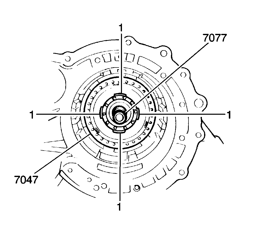
- Position the four tabs of a J 35539 into the four notches inside the transaxle case. These notches are indicated in the illustration by the number 1.
- Tap on the J 35539 lightly with a hammer in order to seat the output shaft (7077) against the rear case cover (705). Do not tap directly on the output shaft, as this may damage to the output shaft.
- Rotate the output shaft in order to test the reduction drive gear and the driven gear for any abnormal gear noise.
Notice: Use the correct fastener in the correct location. Replacement fasteners must be the correct part number for that application. Fasteners requiring replacement or fasteners requiring the use of thread locking compound or sealant are identified in the service procedure. Do not use paints, lubricants, or corrosion inhibitors on fasteners or fastener joint surfaces unless specified. These coatings affect fastener torque and joint clamping force and may damage the fastener. Use the correct tightening sequence and specifications when installing fasteners in order to avoid damage to parts and systems.
Tighten
Tighten the reduction driven gear nut to 150 N·m (108 lb ft).
Tighten
Tighten the rear case cover bolts to 23 N·m (17 lb ft).
Tighten
Tighten the rear case cover nuts to 15 N·m (11 lb ft).
