Tools Required
| • | J 36850 Transjel®
Transmission Assembly Lubricant |
Removal Procedure
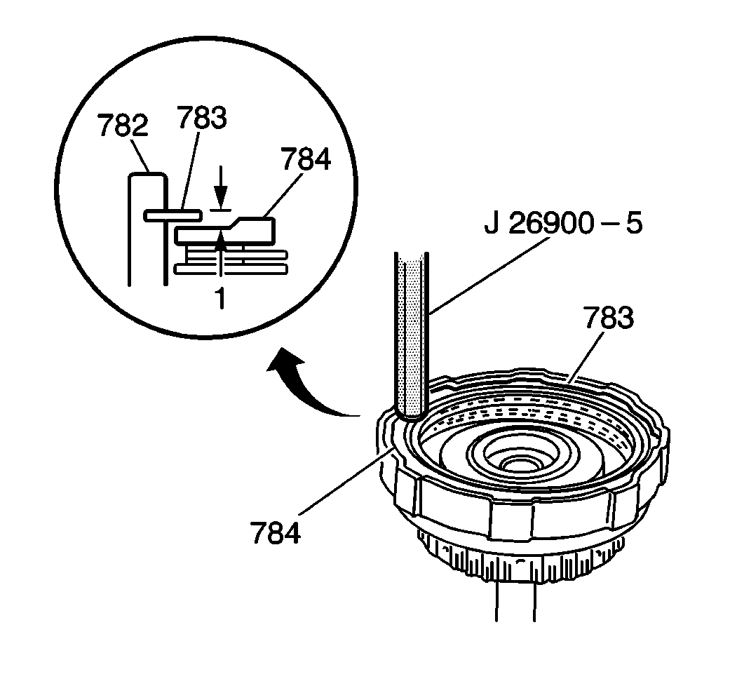
- Measure the clearance
within the forward clutch drum (782) by using a J 26900-5
. Measure the height between the forward clutch plate snap
ring (783) and the forward clutch flange (784). If this height, indicated
in the illustration by the number 1, measures 2.01-2.68 mm (0.079-0.105 in),
then the forward clutch clearance is within specification. If the measurement
is larger than the specification, replace the forward clutch discs or the
plates.
- Remove the input shaft seal rings.
- Remove the direct clutch washer.
- Remove the input shaft bearing and the bearing races.
- Remove the forward clutch plate snap ring (783).
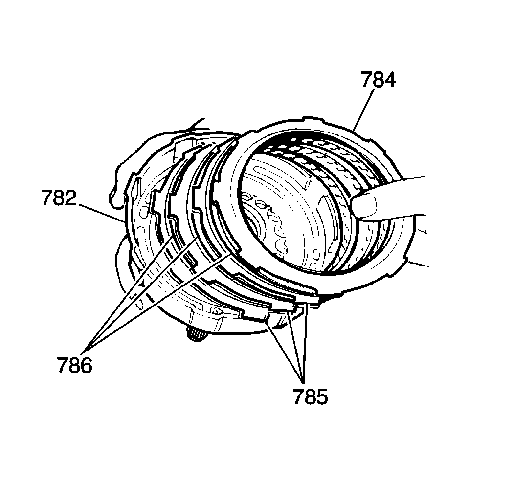
- Remove the forward clutch
flange (784) from the forward clutch drum (782).
- Remove the clutch discs (786) and plates (785).
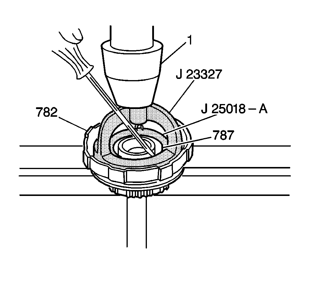
Caution: Use a screwdriver in order to remove the snap ring. Keep your fingers
and hands away from the hydraulic press arbor and from the clutch return spring
seat. Once you have removed the snap ring, release the hydraulic press slowly.
Failure to follow this precaution may result in serious injury.
Important: In the following step, be careful not to compress the forward clutch
spring seat more than is necessary in order to remove the clutch plate snap
ring.
- Install a J 23327
with
a J 25018-A
. Place the
forward clutch drum (782) in a hydraulic press, indicated in the illustration
by the number 1. Slowly compress the forward clutch spring seat until you
are able to remove the clutch plate snap ring (787).
- Remove the forward clutch spring seat snap ring (787).
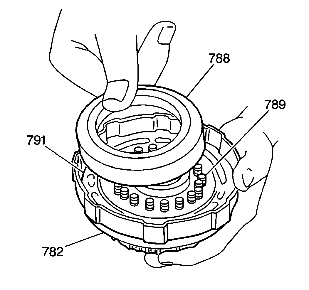
- Remove the forward clutch
spring seat (788). Remove the return spring assembly (789) from the forward
clutch drum (782).
- Locate the forward clutch piston (791).
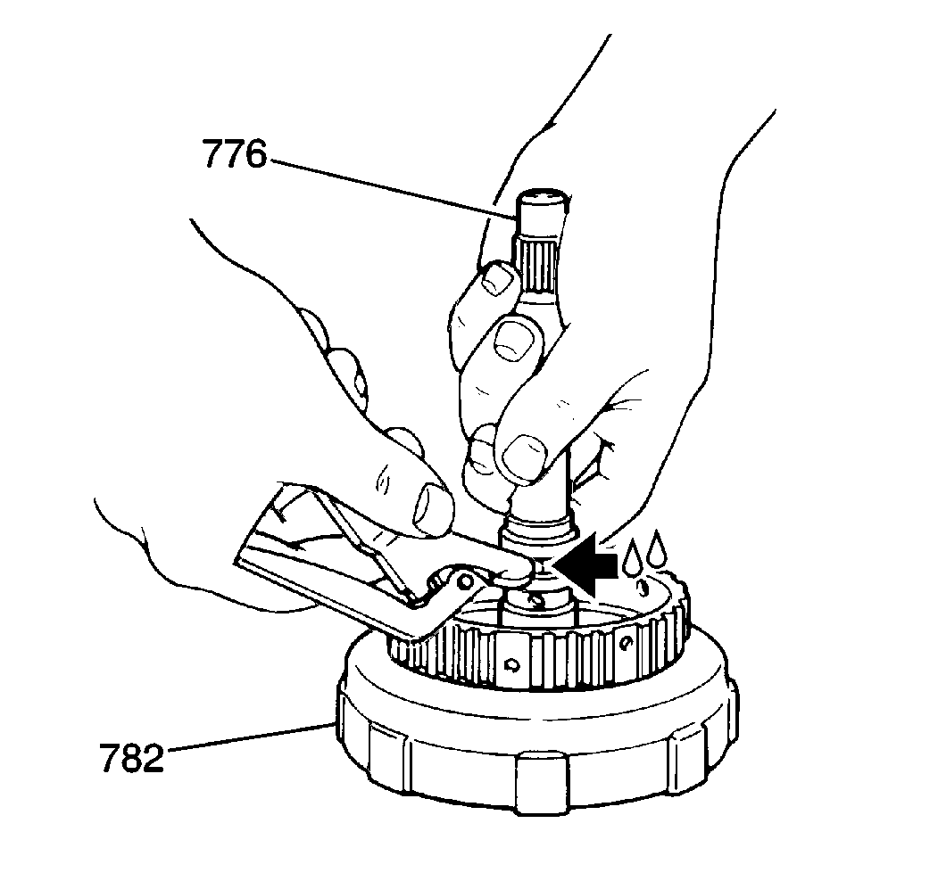
- Remove the forward clutch
piston from the forward clutch drum (782) by gripping the input shaft (776)
and slowly applying low pressure compressed air into the drum fluid inlet
hole, as shown in the illustration. If the piston does not pop out, carefully
lift the piston out with needle nose pliers.
- Remove the forward clutch piston outer seal from the drum. Remove
the forward clutch piston inner seal from the piston.

- Use low pressure compressed
air in order to inspect the forward clutch piston check valve for free movement
and for leakage. If leaks exist, replace the forward clutch piston .
- Inspect the forward clutch drum (782) for the following conditions:
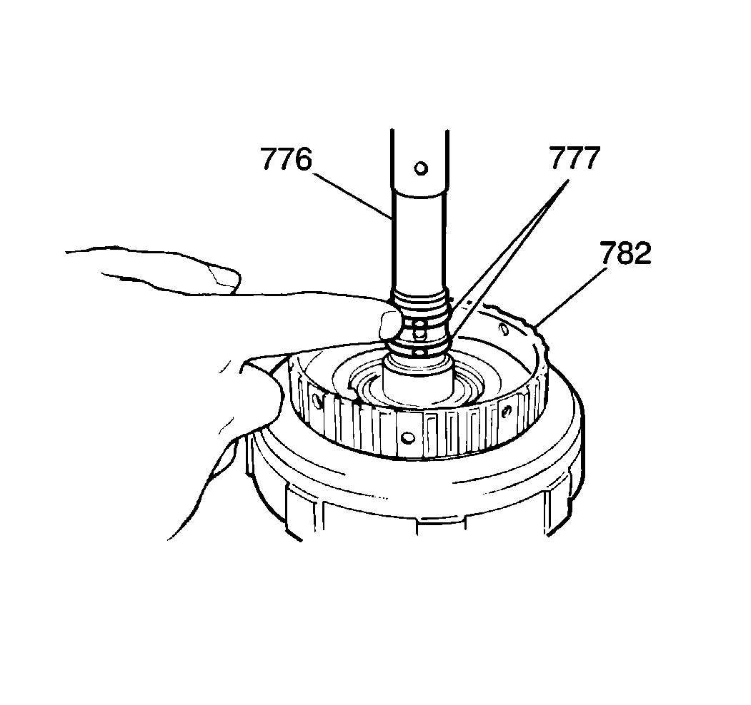
- Inspect the input shaft
(776) and the seal ring grooves (777) for burrs or sharp edges.
Installation Procedure

Important: Do not twist, cut or tear the seals during the following assembly procedure.
- Install a new inner seal to the forward clutch piston (791). Lubricate
with J 36850
.
- Install a new outer seal to the forward clutch piston (791). Lubricate
with J 36850
.
- Install the forward clutch piston (791) into the forward clutch
drum (782).
- Install 18 forward clutch piston return springs (789).
Install the forward clutch return spring seat (788).
Notice: Securely position the forward clutch snap ring into the four projections
of the forward clutch spring seat. Do not compress the return springs more
than necessary in order to install the forward clutch spring seat
snap ring.
- Using a J 23327
with
the J 25018-A
, place the
forward clutch drum in a hydraulic press. Slowly compress the forward clutch
spring seat until you are able to fit the forward clutch plate snap ring.
- Install the forward clutch spring seat snap ring. Securely seal
the snap ring in the four projections of the forward clutch return spring
seat.

Notice: Whenever you install new clutch discs in the firsts-reverse brake, the
forward clutch or the direct clutch assemblies, you must first soak these
discs for two hours in Dexron®-III automatic transmission fluid GM P/N
12341643, or equivalent. This causes the clutch material on the discs to permeate
with the fluid. This will aid in ease of assembly and prevent
clutch overheating on first time engagement.
- Install three clutch plates (785) and three clutch discs (786) into
the forward clutch drum (782) in an alternating sequence, beginning with a
clutch plate (785).
- Install a forward clutch flange (784) into the forward clutch
drum (782).
- Install the forward clutch plate snap ring (783) into the forward
clutch drum (782).

- Use a J 26900-5
in order to determine the clearance
of the forward clutch drum (782). Measure the height between the forward
clutch plate snap ring (783) and the forward clutch flange (784). If this
height, indicated in the illustration by the number 1, measures 2.01-2.68 mm
(0.079-0.105 in), then the forward clutch clearance is within
specification.
- If the measurement falls out of specification with the new forward
clutch discs and plates installed, install a flange of a different thickness.
Two sizes of clutch flanges are available:
| • | Thickness 3.00 mm (0.118 in) |
| • | Thickness 3.37 mm (0.132 in) |
- Inspect the forward clutch piston for operation by slowly applying low
pressure compressed air through the drum fluid inlet hole. The piston should
return to its original position after you release the air pressure.

- Install the input shaft
seal rings (777). Lubricate with J 36850
.
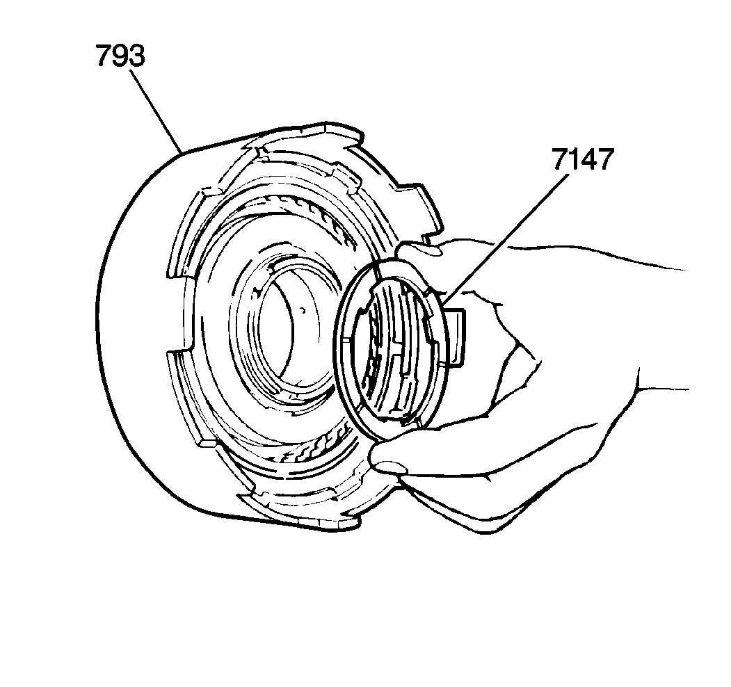
- Align the inner teeth
of the direct clutch discs.
- Install the inner direct clutch washer (7147) to the direct clutch
assembly (793), with the grooved side facing outward, as shown in the illustration.
Lubricate with J 36850
.
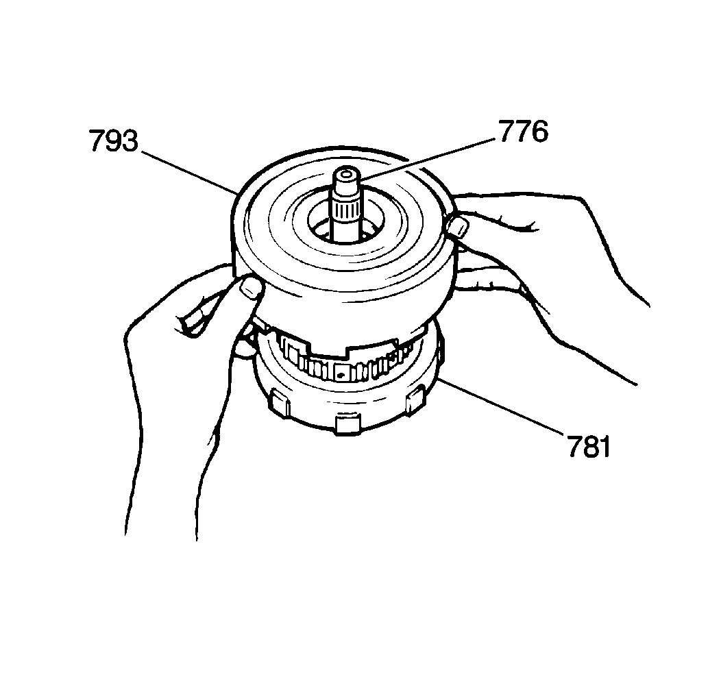
- Install the direct clutch
assembly (793) onto the input shaft (776) and onto the forward clutch assembly
(781). Confirm that the grooves between the teeth of the direct clutch discs
align with the splines of the forward clutch drum. Twist the direct clutch
assembly while working downward onto the forward clutch drum.
- Inspect the direct clutch drum (793) for proper installation by
moving the drum up and down gently by hand. If you have correctly assembled
the direct clutch, you will hear a click sound from the direct clutch drum.
If you do not detect a clicking sound, you may have incorrectly installed
the direct clutch drum. If so, remove the direct clutch drum (793) from the
forward clutch drum (781) and input shaft (776). Reposition as necessary.
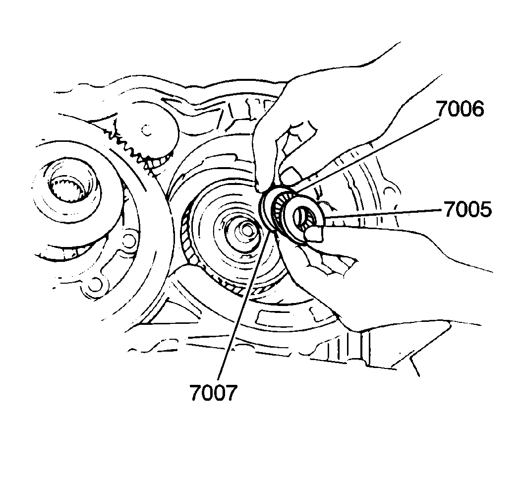
- Lubricate the front planetary
ring gear outer bearing (7006) and lubricate the races (7005, 7007) with J 36850
.
- Install the following parts in the order specified:
| 19.1. | Number 2 race (7007) -- outside diameter 35.8 mm (1.40 in),
flange side down |
| 19.2. | Front planetary ring gear outer bearing (7006) |
| 19.3. | Number 1 race (7005) -- outside diameter 37.9 mm (1.49 in),
flange side down |
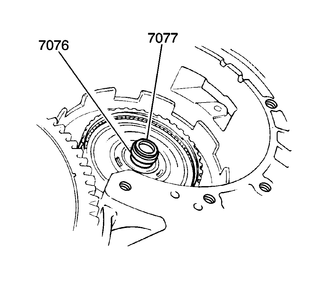
- Align the inner teeth
of the forward clutch discs. Lubricate the output shaft seal ring (7076)
with J 36850
. Install the
ring on the output shaft (7077).
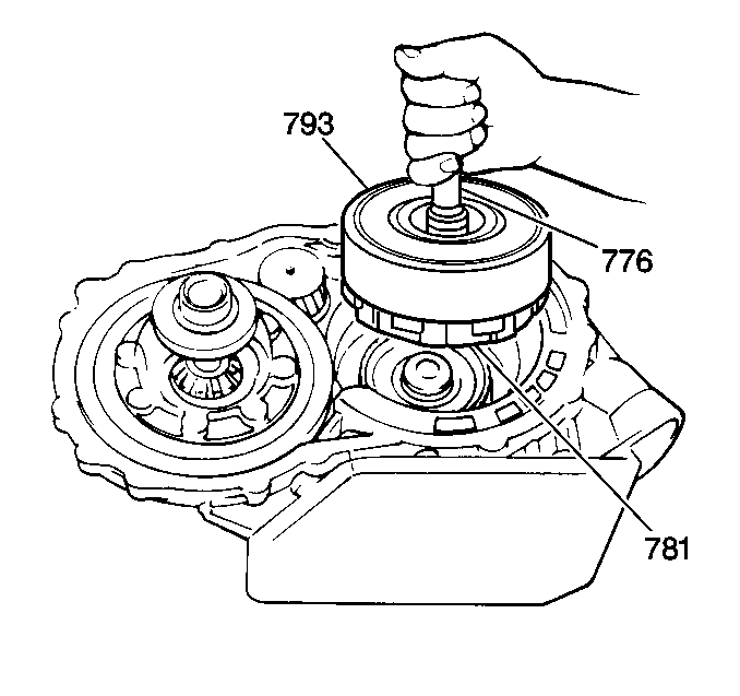
- Install the input shaft
(776) and forward/direct clutch assembly (781/793), by lowering the assembly
onto the front planetary ring gear. Be certain that the grooves between the
teeth of the forward clutch discs align with the splines of the front planetary
ring gear. Twist the assembly while working downward onto the ring gear.
- Inspect the input shaft and the forward/direct clutch assembly
for proper installation by moving the assembly up and down gently by hand.
If you assembled the parts correctly, you will hear a click sound from the
forward clutch drum. If you do not hear the clicking sound, you may have
incorrectly installed the input shaft or the forward/direct clutch assemblies.
If so, remove the input shaft and the forward/direct clutch assembly from
the front planetary ring gear. Reposition as necessary.
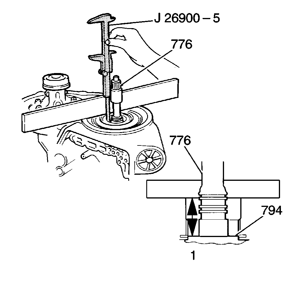
- Measure the input shaft
flange depth by placing a straightedge across the front of the transaxle
case and measure the distance between the top of the input shaft flange and
the bottom of the straightedge with a J 26900-5
. The measurement, indicated in the illustration as the number
1, must fall within 49.82-51.06 mm (1.962-2.010 in).
With the exception of the direct clutch assembly, a measurement that is within
specification confirms that all components are installed correctly. If the
measurement does not fall within the specification, remove the components
and install or reposition these components correctly. Measure the input shaft
flange depth again in order to verify correct installation.
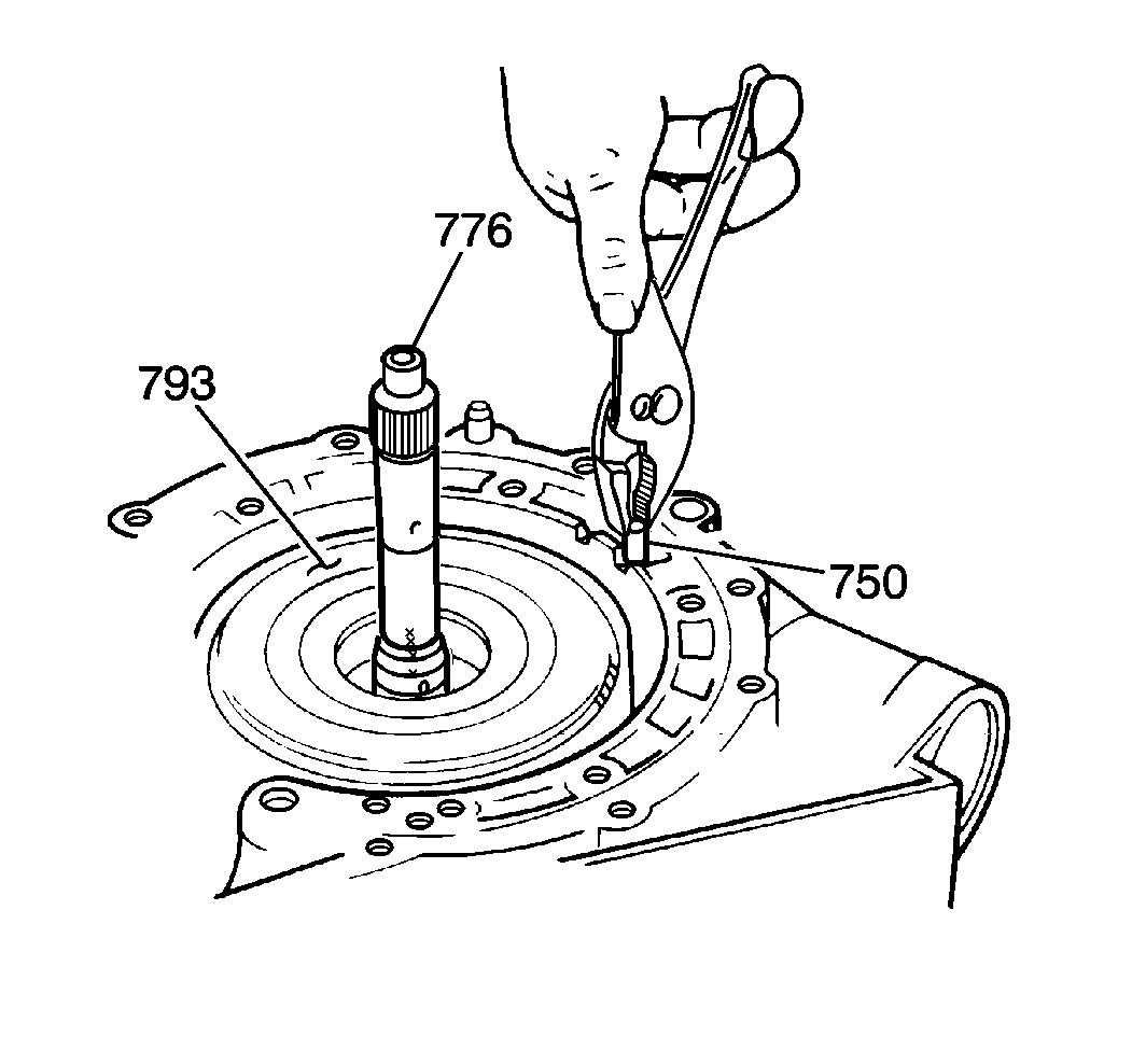
- Lubricate the intermediate
band anchor pin (750) with J 36850
.
- Install the intermediate band anchor pin (750) in the direct clutch
assembly (793) by aligning the strap in the intermediate band with the case
anchor pin hole. Insert the anchor pin.
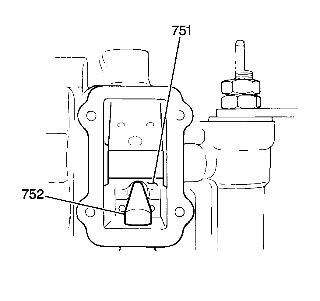
- Confirm that the piston
rod (752) is engaged into the intermediate band (751).
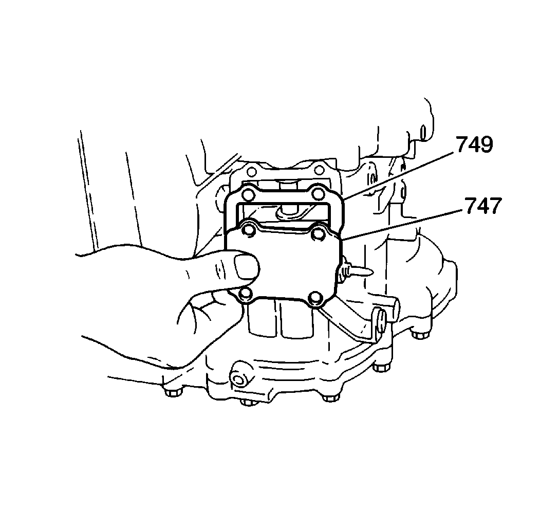
- Install a new intermediate
band cover gasket (749).
- Install the intermediate band cover (747). Attach the cover with
four bolts.
Tighten
Tighten the intermediate band cover bolts to 9 N·m (80 lb in).


