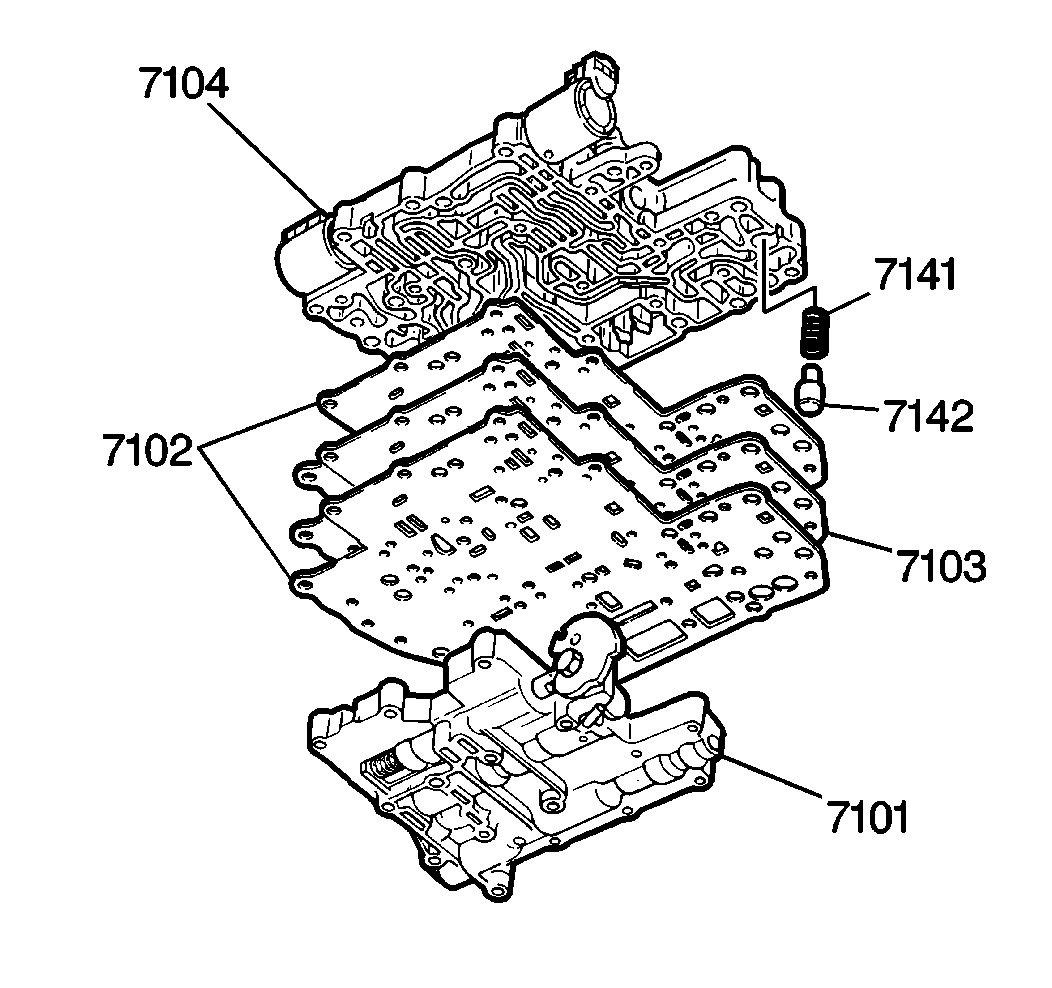
Important: You must install the gaskets and the spacer plate in the correct position
for the fluid to flow through the fluid passages. Misplacement of the gaskets
or the spacer plate will block the fluid passages, and shift failure will
occur. Use caution not to tear or damage the valve body gaskets during installation.
- Install the new valve body gaskets (7102), separated by a spacer plate
(7103) onto the lower valve body (7104).
- Install the lower valve body onto the upper valve body (7101).
Carefully align both halves with their common bolt holes. Confirm that the
cooler bypass valve and spring (7142, 7141) remain in the lower valve body
- Carefully turn the valve body assembly over, so that the upper
valve body (7101) is on the top.
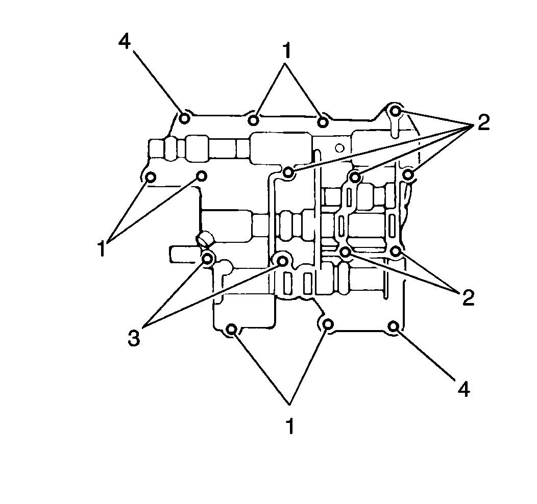
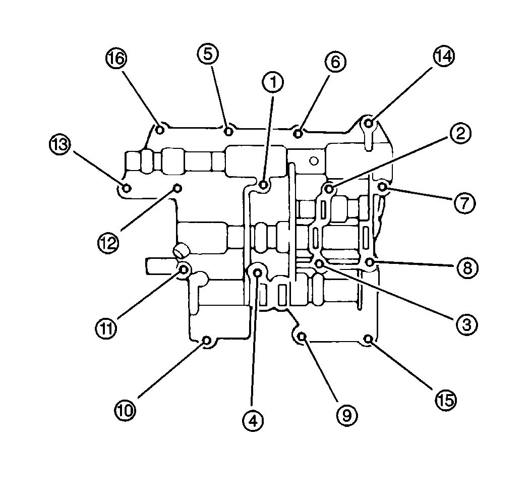
- Install 16 upper valve
body bolts in the following order:
| 4.1. | Install two reamer bolts (positioning bolts) designated in the
illustration by the number 4. Finger tighten only. |
| 4.2. | Install the 16 bolts (designations 1, 2, 3 and 4) in the following
order. Finger tighten only. |
| • | Bolt 4 - Reamer bolt - 2 pieces |
| • | Bolt 3 - 44.0 mm (1.73 in) - 2 pieces |
| • | Bolt 2 - 38.0 mm (1.49 in) - 6 pieces |
| • | Bolt 1 - 29.5 mm (1.16 in) - 6 pieces |
Notice: Use the correct fastener in the correct location. Replacement fasteners
must be the correct part number for that application. Fasteners requiring
replacement or fasteners requiring the use of thread locking compound or sealant
are identified in the service procedure. Do not use paints, lubricants, or
corrosion inhibitors on fasteners or fastener joint surfaces unless specified.
These coatings affect fastener torque and joint clamping force and may damage
the fastener. Use the correct tightening sequence and specifications when
installing fasteners in order to avoid damage to parts and systems.
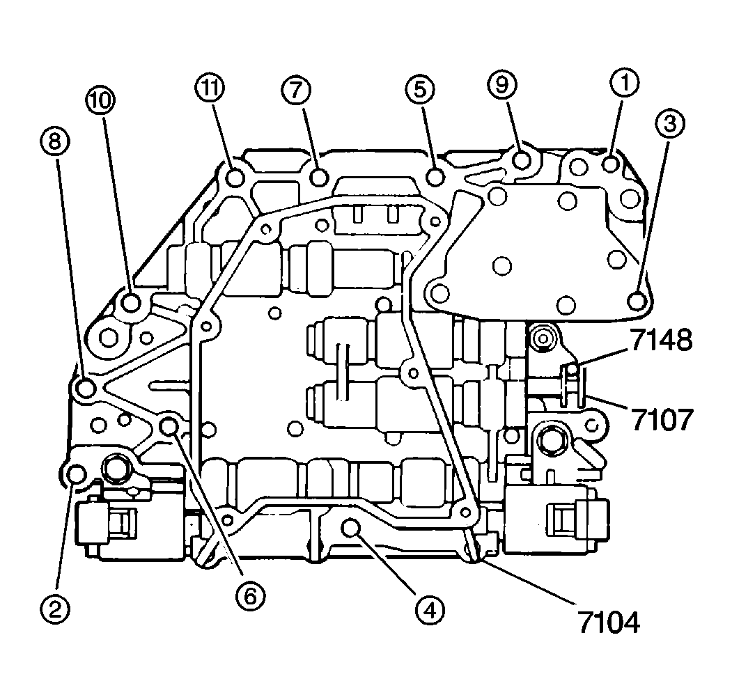
Notice: Torque sequence and specification is very important to valve body operation.
If bolts are torqued at random, valve bores may become distorted and inhibit
valve operation. DO NOT use air powered tools when assembling the valve bodies.
- Tighten the valve body bolts.
Tighten
Tighten all 16 bolts in the order shown to 6 N·m (53 lb in).
Notice: When you install the valve body to the case, confirm that the accumulators
and the springs are in their correct positions and that all valve body bolts
are installed according to length and position. Do not use air
powered tools when you install the valve body assembly.
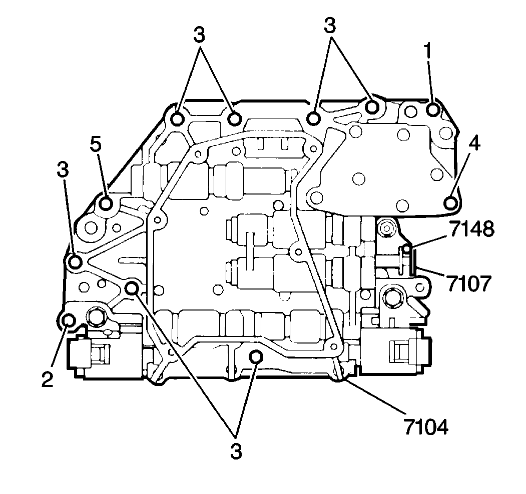
- Install the valve body assembly (7104) to the transaxle case. Align
the manual valve (7107) with the shift lever pin (7148).
- Install 11 lower valve body-to-case bolts (designations 1, 2,
3, 4 and 5) in the following order. Finger tighten only.
| • | Bolt 4 - 47 mm (1.85 in) - 1 piece |
| • | Bolt 3 - 35 mm (1.38 in) - 7 pieces |
| • | Bolt 1 - Reamer bolt: 32 mm (1.26 in) - 1 piece |
| • | Bolt 2 - Reamer bolt: 25 mm (0.98 in) - 1 piece |
| • | Bolt 5 - 25 mm (0.98 in) - 1 piece |
- Tighten the body-to-case
bolts.
Tighten
| • | Tighten the reamer bolts, indicated by the numbers 1 and 2 in
the illustration, to 12 N·m (106 lb in). |
| • | Tighten the remaining lower valve body bolts in the order specified
in the illustration, to 12 N·m (106 lb in). |
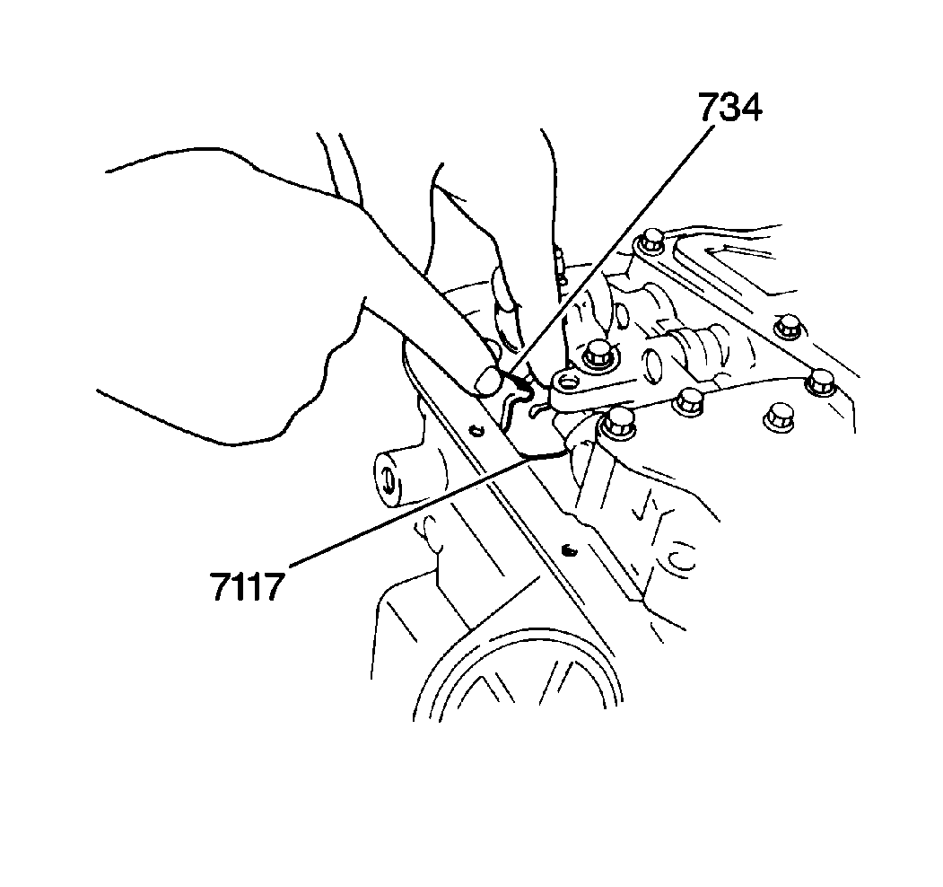
- Install the TV cable assembly
(734) to the transaxle case.
- Install the TV cable to the throttle valve cam (7117).


