Tools Required
Removal Procedure
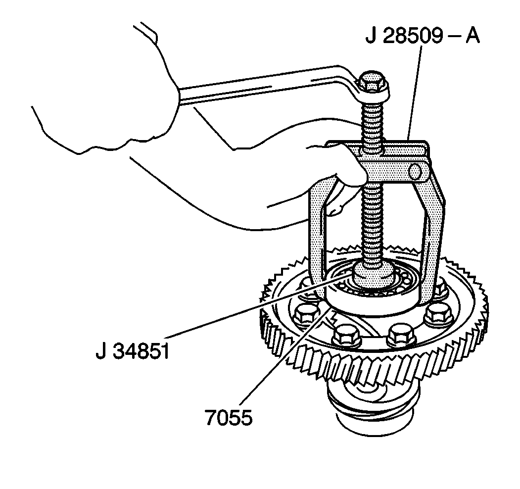
- Using a J 28509-A
with a J 34851
, remove the LH differential side bearing (7055) from the differential
carrier.
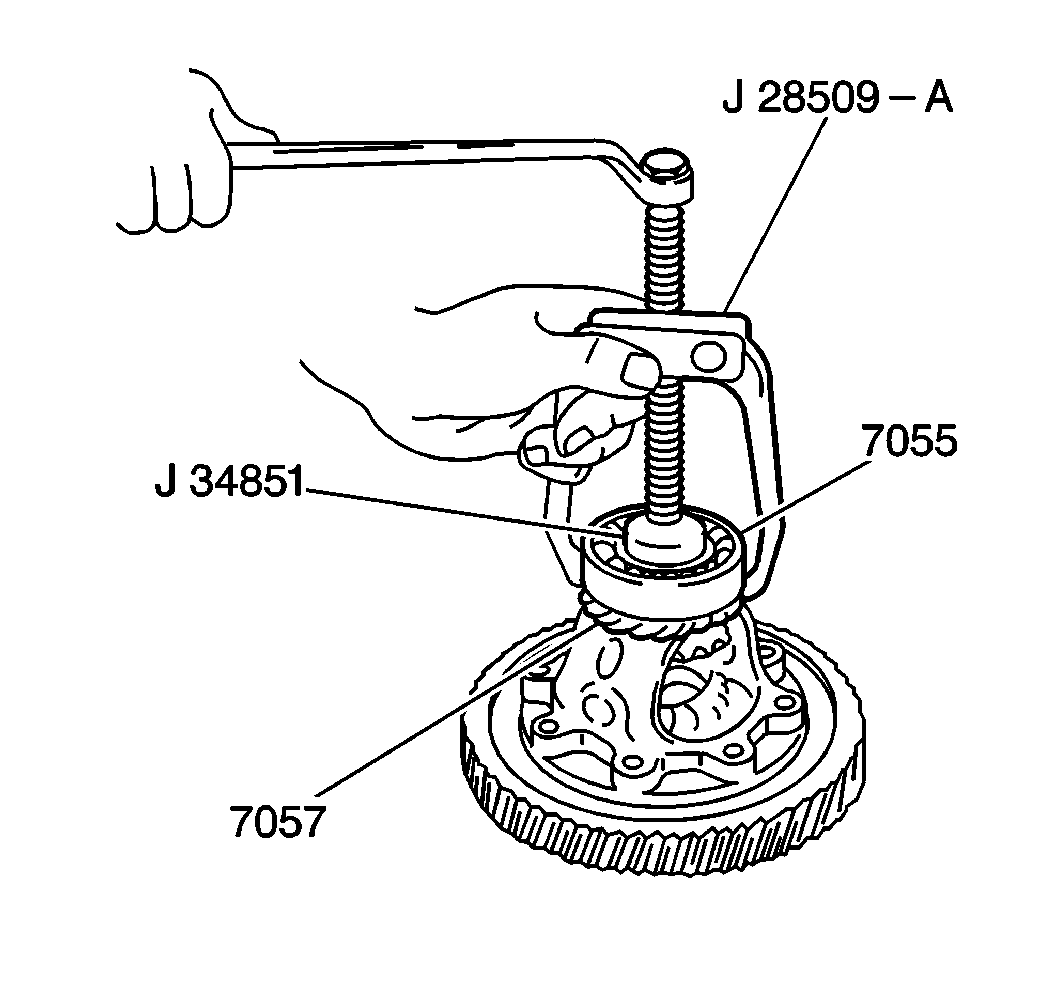
- Using a J 28509-A
with a J 34851
, remove the speedometer drive gear (7057) and the RH differential
side bearing (7055) from the differential carrier.
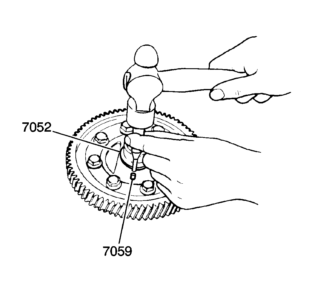
- Using a drift punch remove
the pinion shaft roll pin (7059) from the differential carrier (7052).
Remove the following parts from the differential carrier (7052) (Refer
to Differential Components
):
| • | Ring gear retaining bolts |
- Clean all parts thoroughly with solvent. Air dry.
- Inspect the following parts:
| • | Gear teeth, for signs of damage and excessive or uneven wear |
| • | Pinion gear washers and side gear washers, for signs of excessive
wear, distortion or damage |
Installation Procedure
Notice: Use the correct fastener in the correct location. Replacement fasteners
must be the correct part number for that application. Fasteners requiring
replacement or fasteners requiring the use of thread locking compound or sealant
are identified in the service procedure. Do not use paints, lubricants, or
corrosion inhibitors on fasteners or fastener joint surfaces unless specified.
These coatings affect fastener torque and joint clamping force and may damage
the fastener. Use the correct tightening sequence and specifications when
installing fasteners in order to avoid damage to parts and systems.
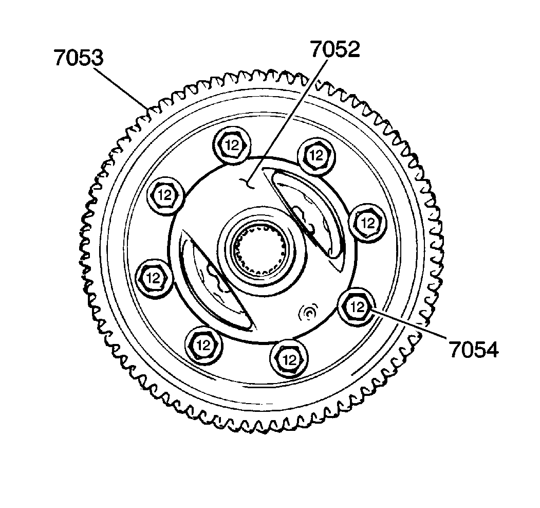
- Install the following parts to the differential carrier (7052)
(Refer to Differential Components
):
| • | The side gear washers and the side gears. |
| • | The pinion gear washers and the pinion gears. |
| • | The pinion gear shaft and the pinion shaft roll pin. |
| • | The ring gear (7053) and the eight retaining bolts (7054). |
Tighten
Tighten the ring gear retaining bolts to 90 N·m (65 lb ft).
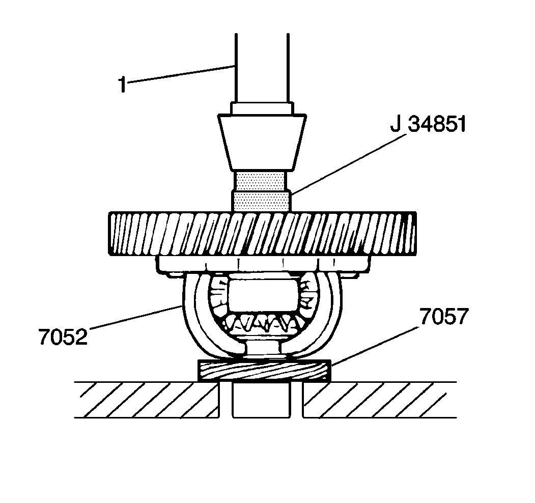
- Using a J 34851
and a hydraulic press, identified in
the illustration by the number 1, install the speedometer drive gear (7057).
Place the gear on the press support and center the differential carrier
(7052) and slowly press the differential carrier into the drive gear.
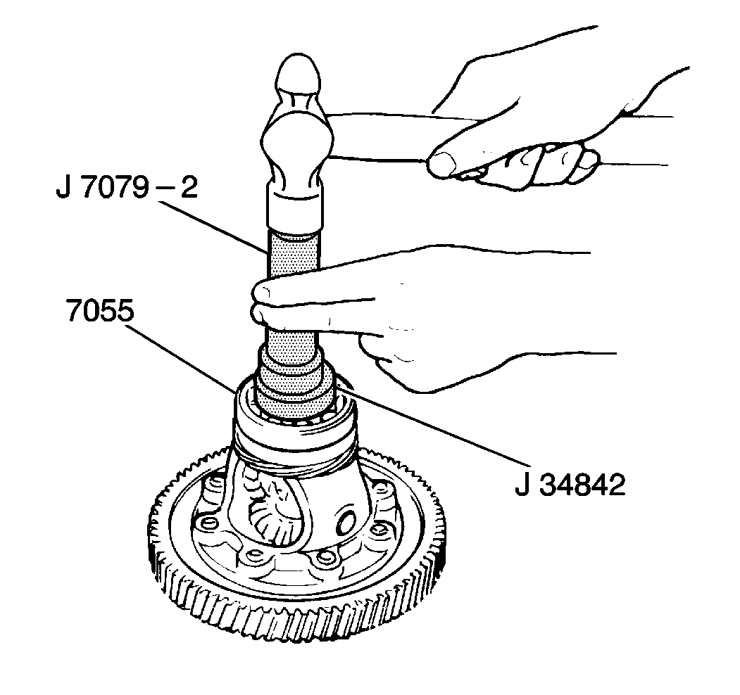
- Using a J 34842
with a J 7079-2
, install the differential side bearings (7055). With the
seal side of the bearings facing the carrier, tap the bearings onto the carrier
evenly.
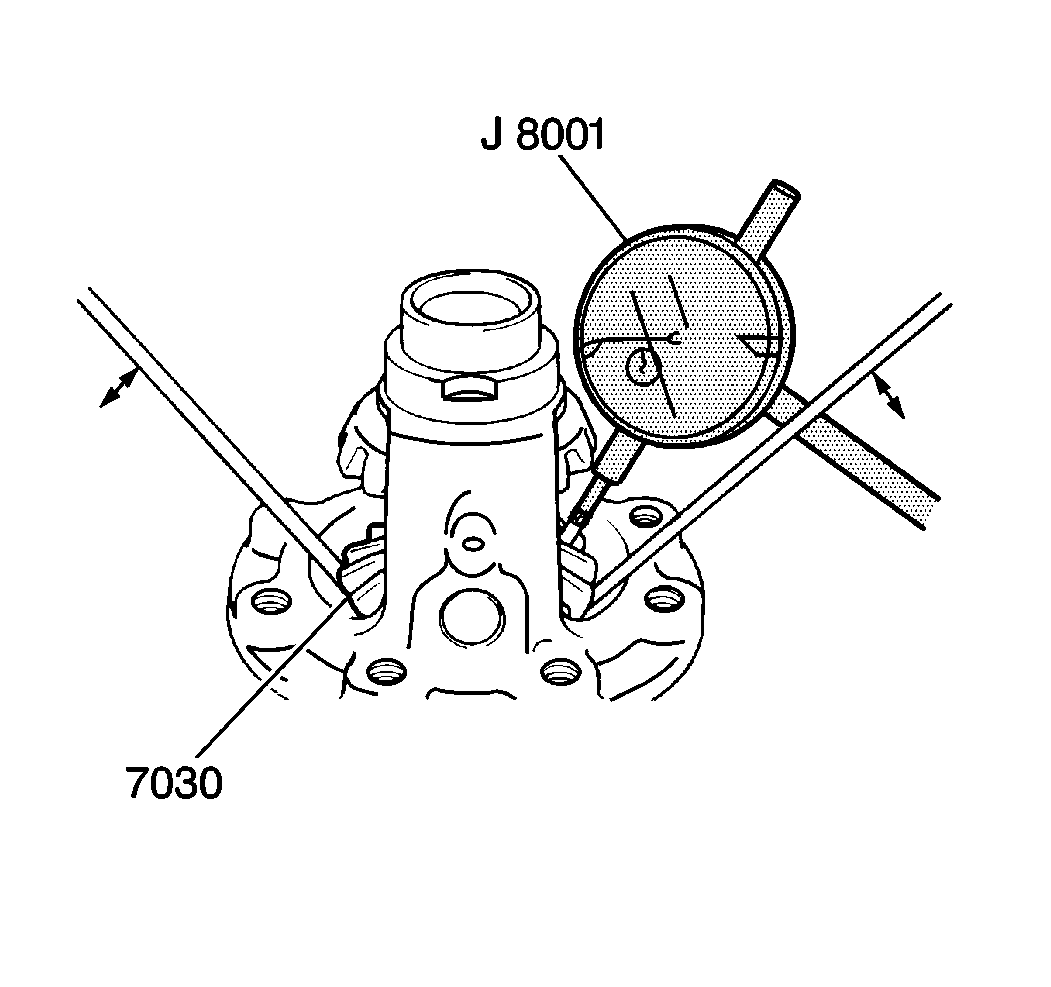
- Using a J 8001
measure the left differential side gear
end play. Place the J 8001
plunger between the teeth of the left differential side gear and move the
left differential side gear up and down using two screwdrivers. Observe
the J 8001
.
- Standard left differential side gear end play should be between
0.05-0.33 mm (0.002-0.013 in). If the left differential
side gear end play falls below 0.05 mm (0.002 in), replace
the left side gear selective shim with the appropriate selective shim in
order to obtain proper left differential side gear end play. Refer to
Side Gear Selective Shim Specifications
Side Gear
Selective Shims Table.
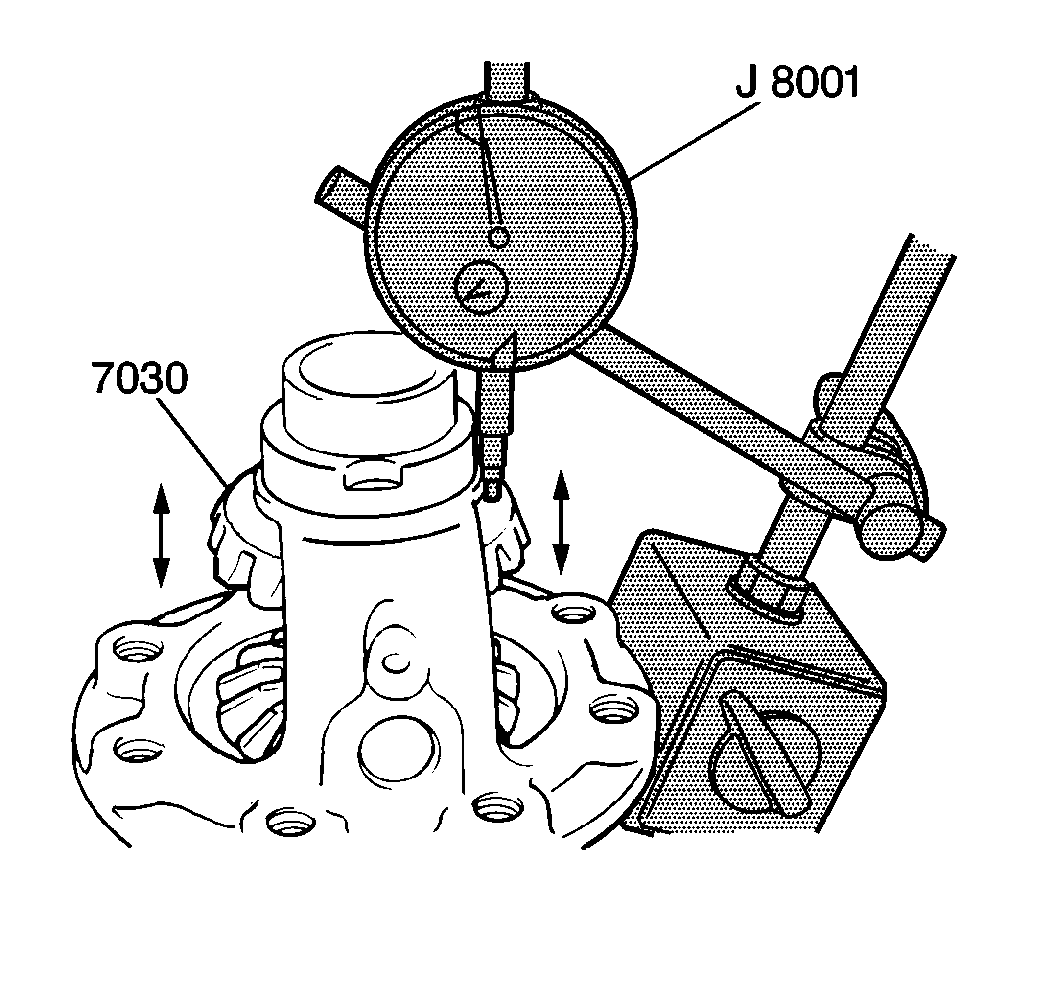
- Using a J 8001
measure the right differential side gear
end play. Place the J 8001
plunger on the rear of the right differential side gear and gently move
the right differential side gear up and down using the fingertips of both
hands. Observe the J 8001
.
- Standard right differential side gear end play should be between
0.05-0.33 mm (0.002-0.013 in). If the right differential
side gear end play falls below 0.05 mm (0.002 in), replace
the right side gear selective shim with the appropriate selective shim in
order to obtain proper left differential side gear end play. Refer to
Side Gear Selective Shim Specifications
Side Gear
Selective Shims Table.


