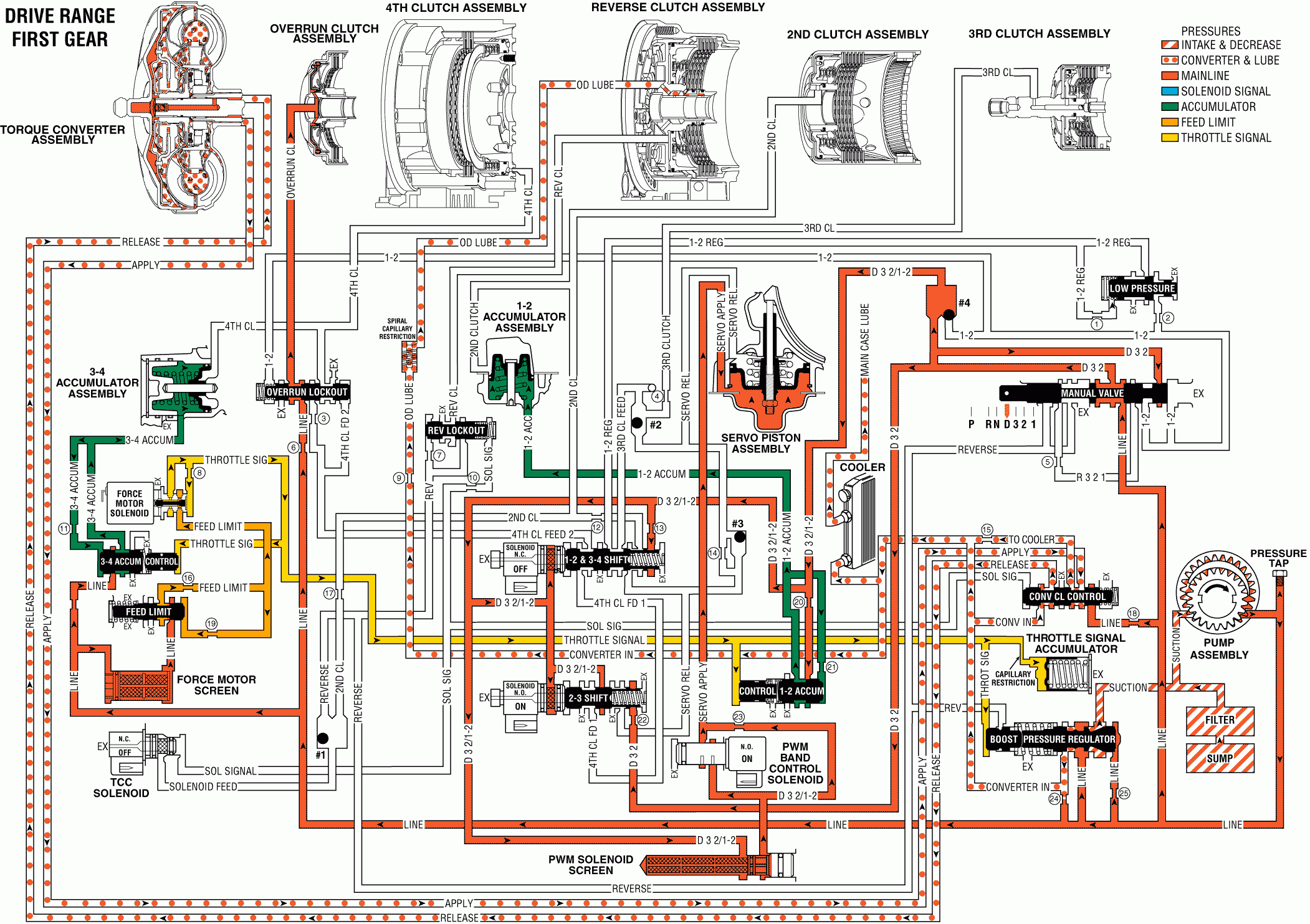
For 1990-2009 cars only
When the gear selector lever is moved to the Overdrive range position (D), from either Park or Neutral, the following changes occur to the transmissions hydraulic and electrical systems:
Manual Valve: In the Overdrive range position line pressure enters the D32 fluid circuit. D32 fluid is routed to the end of the manual valve where it is blocked by a valve land.Mode Switch: Signals the TCM that the selector lever and manual valve are in the Overdrive range (D) position.
Checkball #4: Located in the main case, it is seated against the empty 1-2 fluid circuit by D32 fluid pressure from the manual valve. D32 fluid fills the D32/1-2 fluid circuit.
Brake Band Applies
Pulse Width Modulated (PWM) Solenoid Screen: Located in the main case valve body, it filters D32/1-2 fluid that feeds the PWM band apply solenoid.PWM Band Apply Solenoid: The TCM energizes the solenoid and controls the solenoid's duty cycle depending on vehicle application and operating conditions. The duty cycle determines the rate at which the solenoid regulates D32/1-2 fluid into the servo apply fluid circuit.
Orifice #17 (Between D32/1-2 and Servo Apply): D32/1-2 fluid also feeds the servo apply fluid circuit through this orifice. The orifice allows servo apply fluid to exhaust during a shift from Overdrive Range (D) to Park, Reverse or Neutral. During this shift the PWM solenoid is at 100% duty cycle (closed). Therefore, exhausting servo apply fluid is blocked at the closed solenoid and must exhaust through this orifice, into the D32/1-2 fluid circuit and past the 1-2 accumulator valve.
Servo Piston: Servo apply fluid pressure acting on the piston overcomes the force of both the servo cushion (99) and servo return (103) springs. This moves the piston and apply pin (102) to apply the brake band and obtain First gear. These spring forces help control the apply rate of the brake band.
1-2/3-4 Shift Solenoid: De-energized (OFF) as in Park, Reverse and Neutral, the solenoid is closed and blocks D32/1-2 fluid pressure from acting on the solenoid end of the valve.
1-2/3-4 Shift Valve: Spring force and D32/1-2 fluid pressure acting on the spring end of the valve keep the valve in the First and Fourth gear position.
2-3 Shift Solenoid: Energized (ON) as in Park, Reverse and Neutral, the solenoid is closed and blocks D32/1-2 fluid pressure from acting on the solenoid end of the valve.
2-3 Shift Valve: Spring force and D32 fluid pressure keep the valve in the First and Second gear position. In this position the valve blocks the D32/1-2 fluid circuit at the middle land of the valve.
1-2 Accumulator Valve Train: D32/1-2 fluid is regulated through the 1-2 accumulator valve (320) and into the 1-2 accumulator fluid circuit. This fluid regulation is controlled by throttle signal fluid pressure, spring force and orificed 1-2 accumulator fluid pressure. Note: The 1-2 accumulator control valve spring (319) is not used on all models.
1-2 Accumulator Piston: 1-2 accumulator fluid pressure assists 1-2 accumulator piston spring (316) force acting on the piston. This keeps the piston in the First gear position in preparation for a 1-2 upshift.
Force Motor Solenoid: As in Park, Reverse, Neutral and all other gear ranges, the TCM controls the solenoid to regulate feed limit fluid into throttle signal fluid pressure in relation to vehicle operating conditions.
Overdrive Range, First Gear

