For 1990-2009 cars only
Tools Required
J 3387-2 Guide Pins
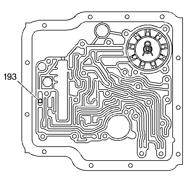
- Install the check ball (193) into the case fluid passages.
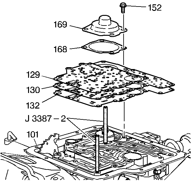
- Install J 3387-2 into the transmission case.
- Install the spacer plate to transmission case gasket (132).
- Install the spacer plate (130).
- Install the control valve body to spacer plate gasket (129).
- Install the servo cover gasket (168).
- Install the servo cover (169).
- Install the servo cover bolts (152).
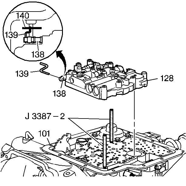
- Install the manual valve link (139) into the manual valve (138). The long side of the manual valve link (139) fits into the manual valve (138).
- Install the control valve body assembly (128) onto the transmission case (101). Connect the manual valve link (139) to the detent lever (140).
- Remove J 3387-2 .
- Install the manual detent roller assembly (145).
- Install the control valve body bolts (155).
- Install the reinforcement plate (146).
- Install the reinforcement plate bolts (152).
- Install the governor oil pressure switch (137).
- Install the oil pressure switch (176), if equipped.
- Install new seals (151) onto the TCC solenoid pipes (149) and (150).
- Install the solenoid pipes (149) and (150) into the TCC solenoid (147).
- Install the pipes (149) and (150) into the control valve assembly (500) and the transmission oil pump.
- Install the TCC solenoid bolts (152).
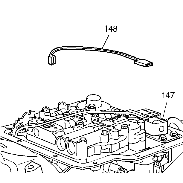
- Install the wiring harness (148).
- Connect the wiring harness to the electrical components.
Tighten
Tighten the bolts to 24 N·m (18 lb ft).
Refer to Fastener Notice .
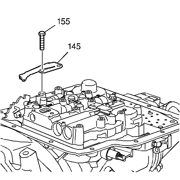
Tighten
Tighten the bolt to 19 N·m (14 lb ft).
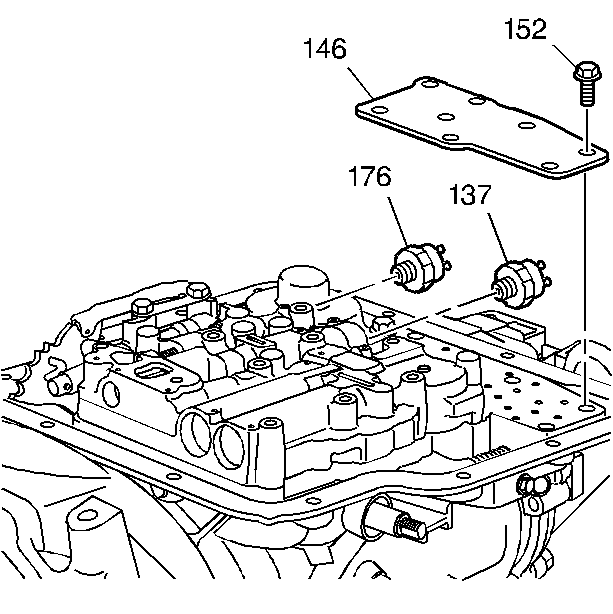
Tighten
Tighten the pressure switch to 10 N·m (89 lb in).
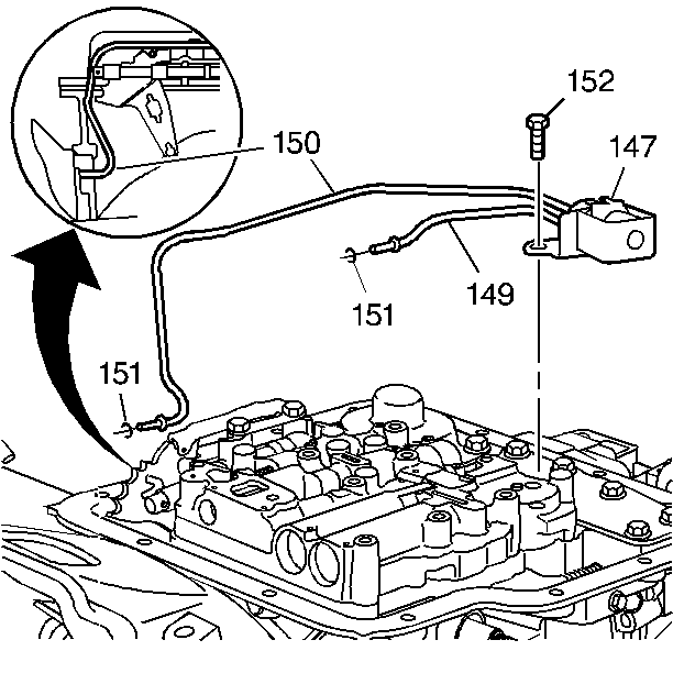
Important:: Make sure the TCC Solenoid pipes do not interfere with the manual valve operation.
Tighten
Tighten the bolts to 19 N·m (14 lb ft).
