Diagnosis will be much easier once you have identified
the vibration as first-order of driveline rotation during the road test. Next
identify the exact area of the vibration and take proper action.
In most cases, vibration may be reproduced in the stall where the vibration
may be better or worse than that experienced during the road test, this is
normal.
The objective is to reduce the vibration to the lowest point possible
in the stall, then evaluate the results during a road test. Many times, a
vibration you were only able to reduce drastically in the
stall will be completely eliminated on the road.
The cause of first-order driveline vibration is usually due to excessive
runout or an imbalanced component.
The following procedure offers a systematic process of elimination in
order to determine which component is at fault:
- Raise the vehicle to curb height. Support the vehicle on a hoist
or heavy stands. Refer to
Lifting and Jacking the Vehicle
in General Information.
- Remove the rear tire/wheel assemblies, then install the wheel
nuts to securely retain the brake rotors to the wheel hubs. Refer to
Tire and Wheel Removal and Installation
in Tires and Wheels.
- Start the engine.
- Place the transmission in gear.
- Accelerate the vehicle to the speed at which the vibration was
most severe.
- Record whether the vibration was present, and at what speed.
- If the vibration is NOT present, the vibration is most likely
sensitive to torque. Refer to Diagnosis of 1st Order Vibration -- Torque
Sensitive.
- If the vibration IS present, determine which end of the rear axle
differential case is vibrating the most.
Important: Check to make sure the engine exhaust system is cool prior to placement
of vibration sensor.
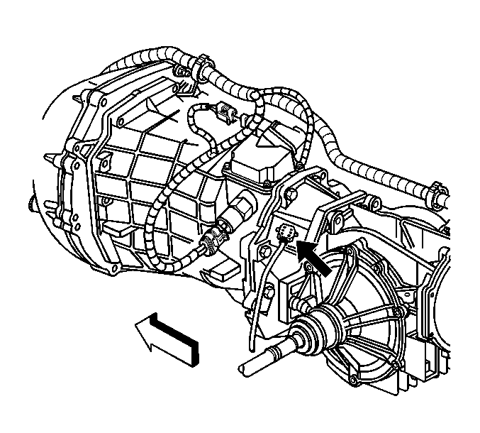
| 8.1. | Place the EVA vibration
sensor on top of the rear axle differential, first at the rear (over the ring
and pinion gear set), then move to the front (over the transmission
output shaft at the transmission). |
| | Important: Check to make sure the vibration sensor cord does not come in contact
with the exhaust system during diagnostic testing.
|
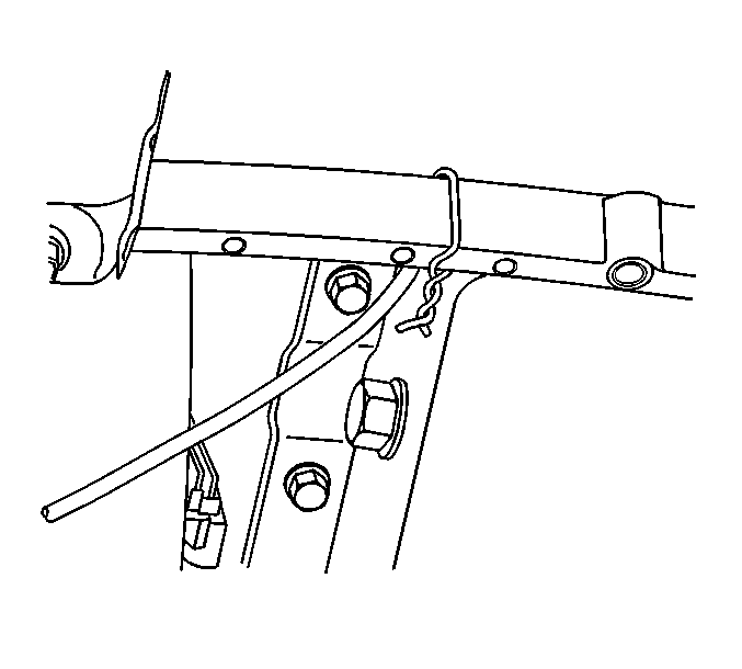
| 8.2. | Using tie straps, strap
the sensor cord out of the way. |
| 8.3. | Accelerate the vehicle to the speed at which the vibration was
most severe and check the EVA frequencies. |
- If the EVA is not picking up any high frequency readings to indicate
a vibration concern, check the front bearing housing on the propeller shaft.
| | Important: Check to make sure the engine exhaust system is cool prior to placement
of vibration sensor.
|
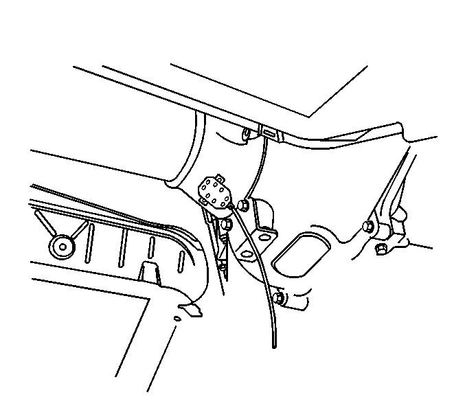
| 9.1. | Place the EVA vibration
sensor on the front bearing housing assembly. |
| | Important: Check to make sure the vibration sensor cord does not come in contact
with the exhaust system during diagnostic testing.
|

| 9.2. | Using tie straps, strap
the vibration sensor cord out of the way. |
| 9.3. | Accelerate the vehicle to the speed at which the vibration was
most severe and check the EVA frequencies. |
- If the EVA is not picking up any high frequency readings to indicate
a vibration concern, check the rear bearing housing on the propeller shaft.
| | Important: Check to make sure the engine exhaust system is cool prior to placement
of vibration sensor.
|
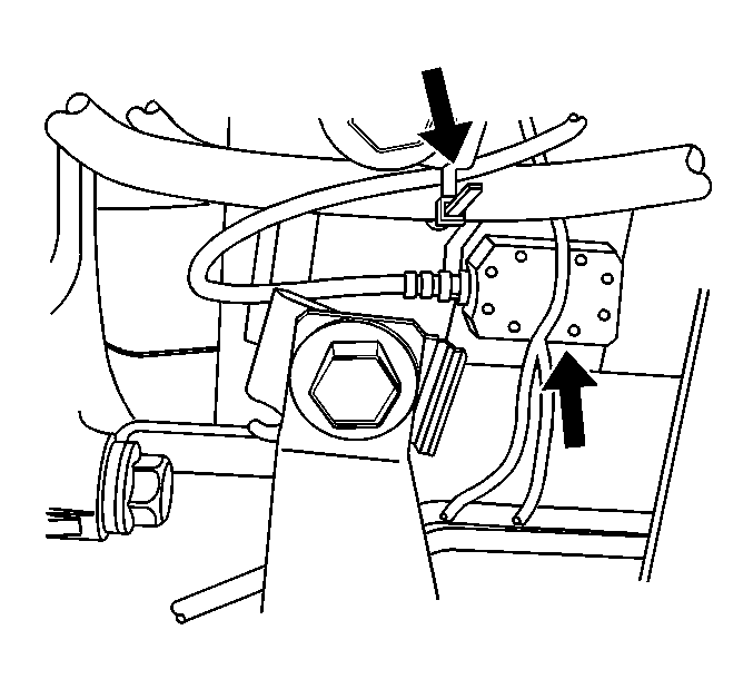
| 10.1. | Place the EVA vibration
sensor on the rear bearing housing. |
| | Important: Check to make sure the vibration sensor cord does not come in contact
with the exhaust system during diagnostic testing.
|
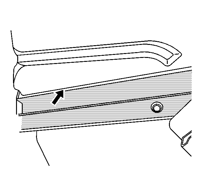
| 10.2. | Using tie straps, strap
the vibration sensor cord out of the way. Run the cord along the inside of
the fuel tank strap and into the passenger door. |
| 10.3. | Accelerate the vehicle to the speed at which the vibration was
most severe and check the EVA frequencies. |
- If propshaft runout is suspected at this point, perform a driveline
support assembly inspection. Refer to Driveline Support Assembly Clean and Inspect
in Driveline/Axle.
First-Order Driveline Vibration Analysis (Torque Sensitive)
If the following conditions are true, the internal rear axle components
are the probable cause of the vibration:
| • | The vehicle has a vibration that is equal to first-order driveline
rotation, and the vibration is not present when testing the vehicle in the
stall. |
| • | You were able to correct the vibration in the stall, but the vibration
returned during the road test. |
Internal rear axle vibrations may be aggravated by the load of the vehicle
working against the ring and pinion gear seat.
Since the propeller shaft and the pinion gear are bolted together through
the pinion flange, the propeller shaft and the pinion gear operate at the
same speed. Vibration in the pinion gear will therefore
have the same frequency and symptoms as the propeller
shaft.
In order to isolate the vibration to the pinion gear, use the following
procedure:
- Raise the vehicle to curb height. Support the vehicle on a hoist
or on safety stands. Refer to
Lifting and Jacking the Vehicle
in General Information.
- Remove the tire/wheel assemblies then install the wheel nuts to
securely retain the brake rotors to the wheel hubs. Refer to
Tire and Wheel Removal and Installation
in Tires
and Wheels.
- With the aid of another technician, accelerate and decelerate
the vehicle through the speed range at which the vibration was noticed during
the road test.
Example
| • | If the vibration was originally noticed at 88 km/h (55 mph),
accelerate from 72 km/h (45 mph) to 107 km/h
(65 mph). Then decelerate from 107 km/h
(65 mph) back to 72 km/h (45 mph). |
| • | Repeat the above step and note whether or not the pinion nose
vibrates under load during acceleration and/or deceleration. |
If the vibration does not occur during the above procedure, install
the tire/wheel assemblies, adding additional load on the
system. Then repeat the above test.
Ensure that both axle shafts rotate at the same speed. The differential
may mask a vibration when one tire is spinning faster than the other tire.
Adjust the brakes in order to correct unequal tire
rotation speed.
If you are unable to reproduce the vibration in the stall, apply the
brake lightly in order to load the system further. Maintain the vehicle speed
at which the vibration was noticed. Do not overheat
the brakes.
If the pinion nose vibrates under acceleration and/or deceleration,
and the other driveline components are eliminated as the cause of the vibration,
then one of the following conditions may cause the
vibration:
| • | A high spot on the pinion gear |
| • | A cocked pinion bearing |
| • | An improper axle housing bore |
Anything that effects the pinion gear and how the pinion gear contacts
the rotating ring gear may contribute to a first-order, torque-sensitive driveline
vibration. The only way to correct the condition is
to replace the faulty components. In most cases, you
must replace the ring and pinion gear set and the
related bearings. In some cases, you must replace the axle
housing. Complete a close-up visual inspection for damage
or unusual wear in order to measure or identify the
specific faulty component.
It is possible to isolate an internal axle vibration.
Once you correct the internal axle problem, road test the vehicle. Inspect
the vehicle for vibration. Balance the driveline, as necessary, in order to
eliminate any remaining vibration.


