For 1990-2009 cars only
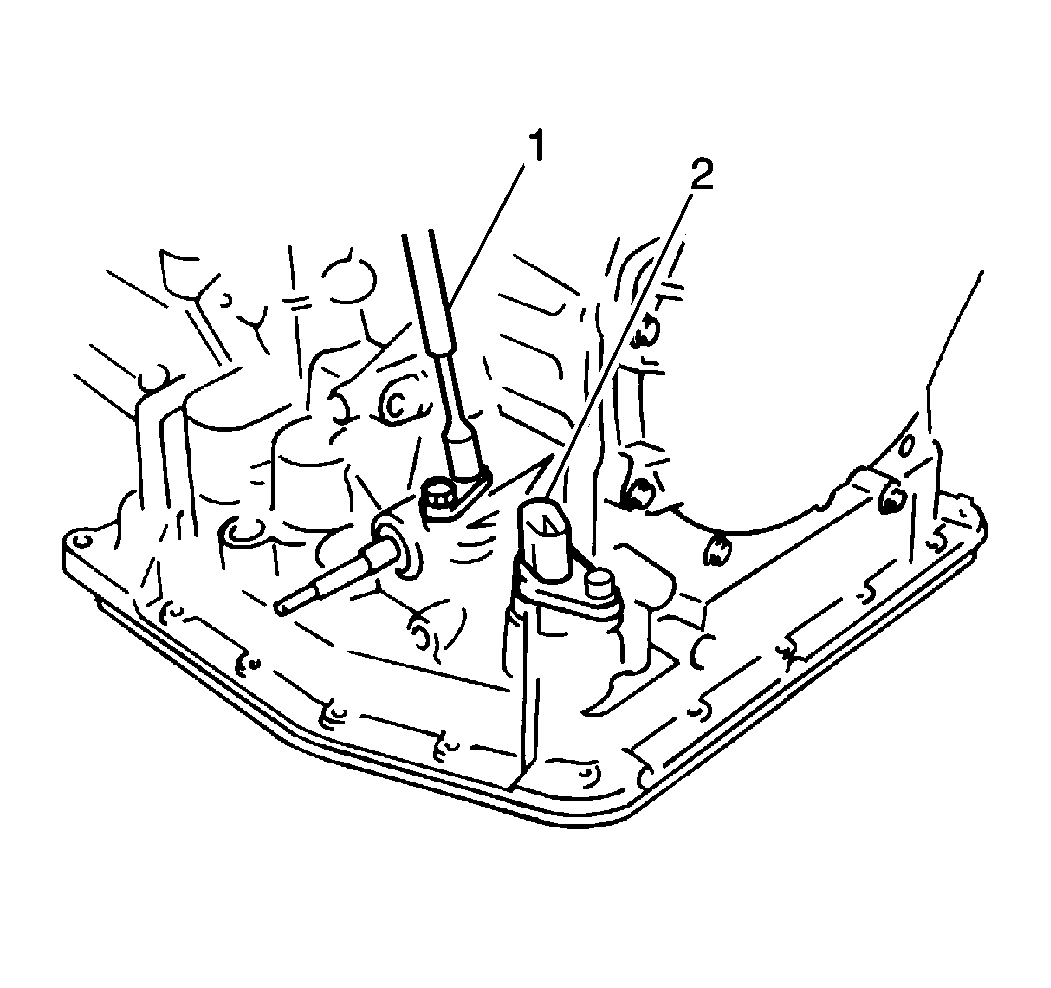
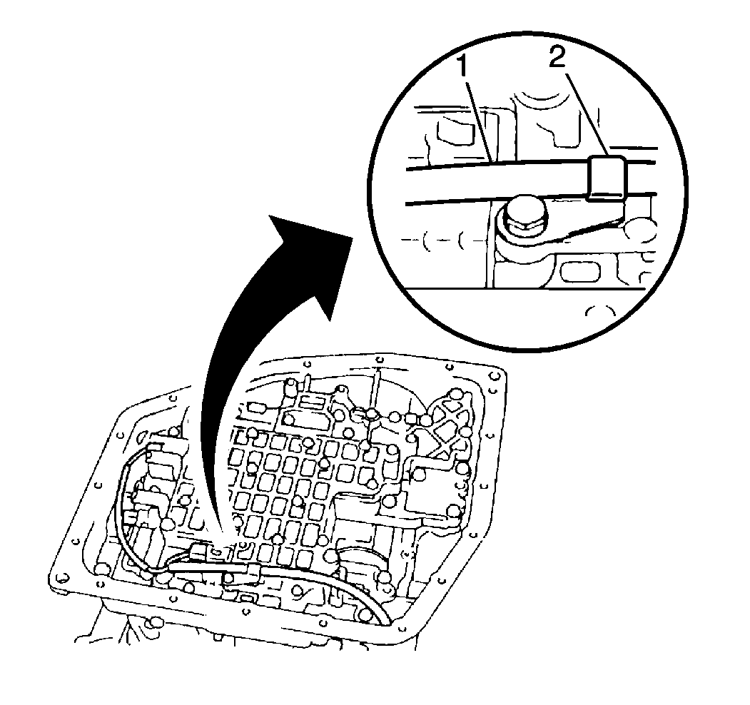
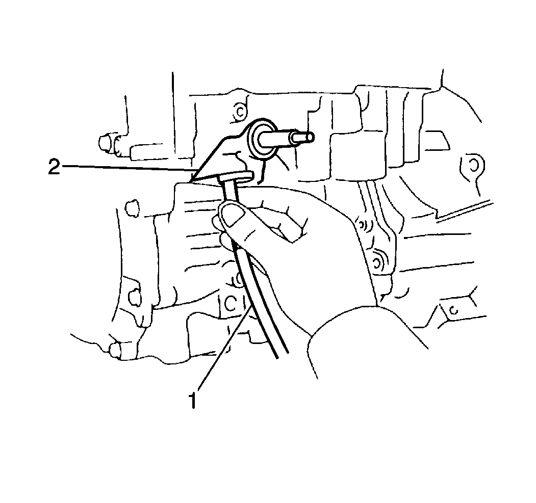
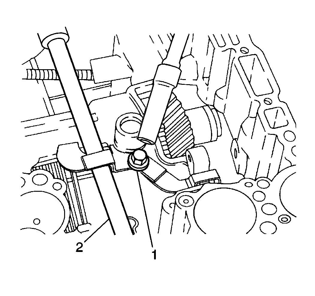
- Remove the TV cable retaining bolt from the TV cable (1).
- Remove the solenoid wire harness retaining bolt from the solenoid wire harness (2).
- Remove the following components from the transaxle case (1):
- Remove the following from the valve body assembly (1):
- Remove the electrical connectors (1) from the following components:
- Remove one bolt and the solenoid wire harness clip (2) from the valve body assembly.
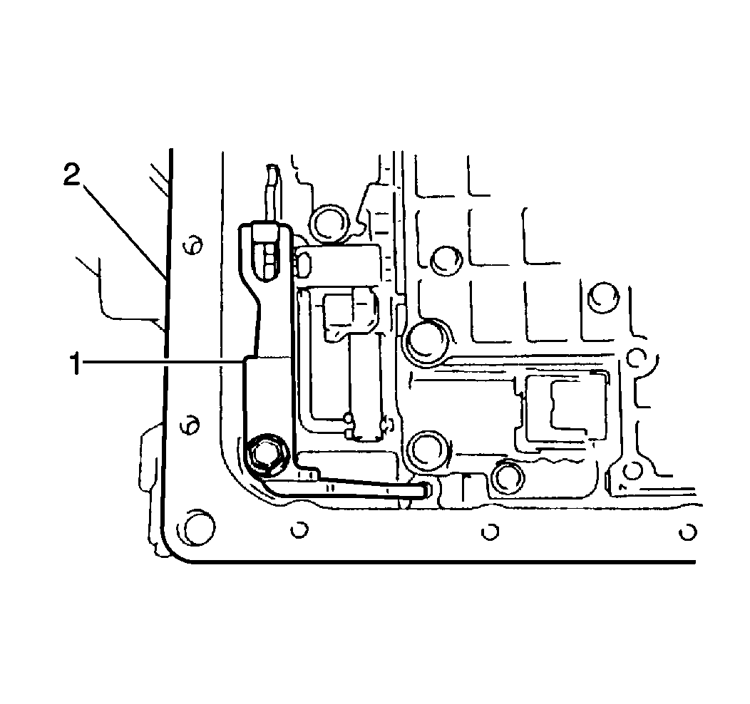
- Remove the solenoid wire harness (1) from the transaxle case (2).
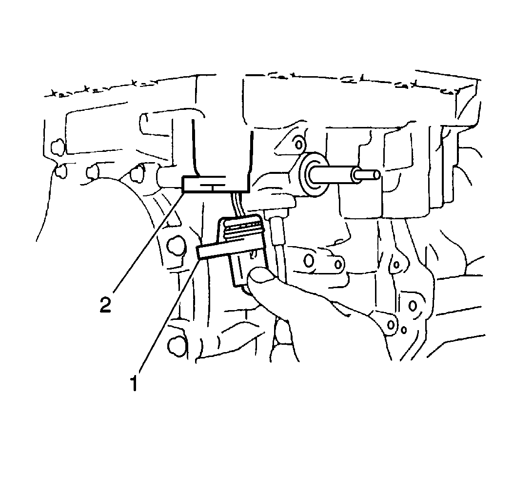
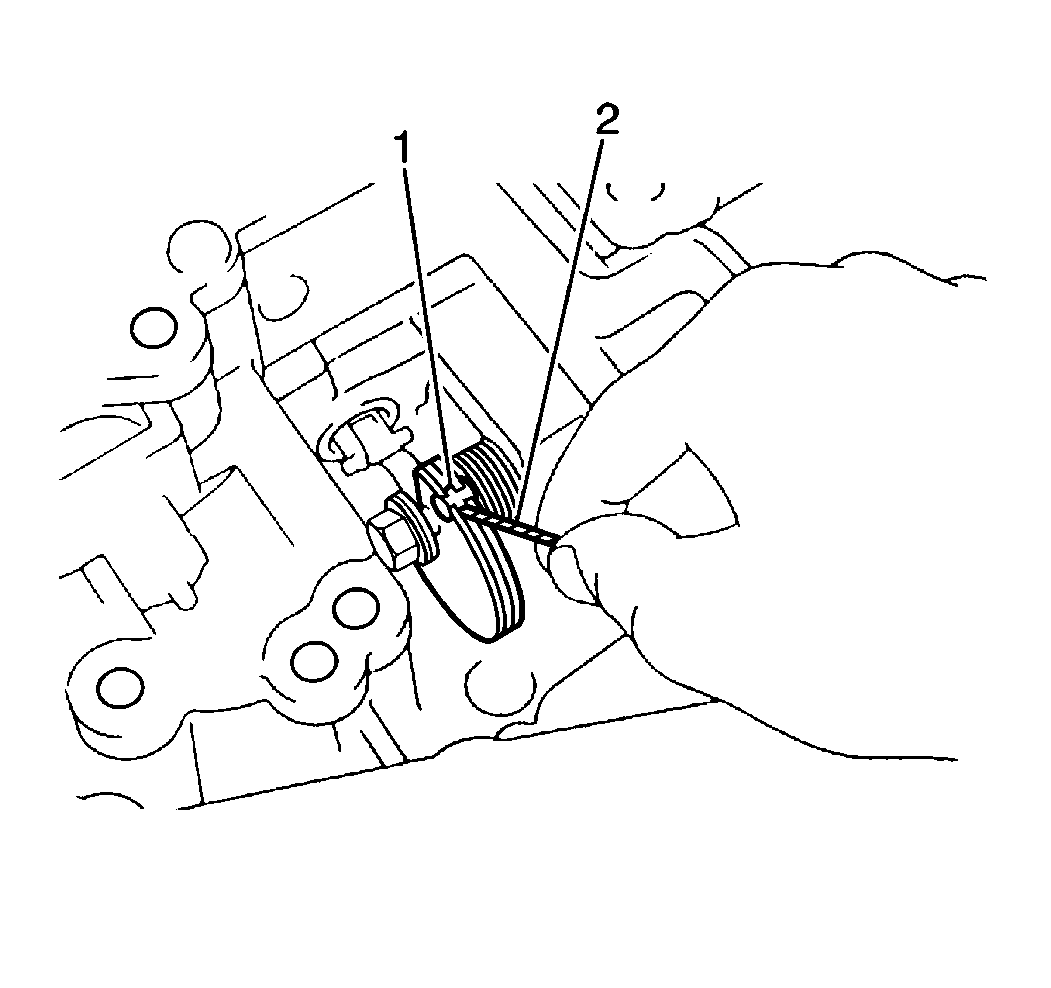
- Disconnect the TV cable (1) from the throttle valve cam (2).
- Remove the TV cable (1) from the transaxle case (2).
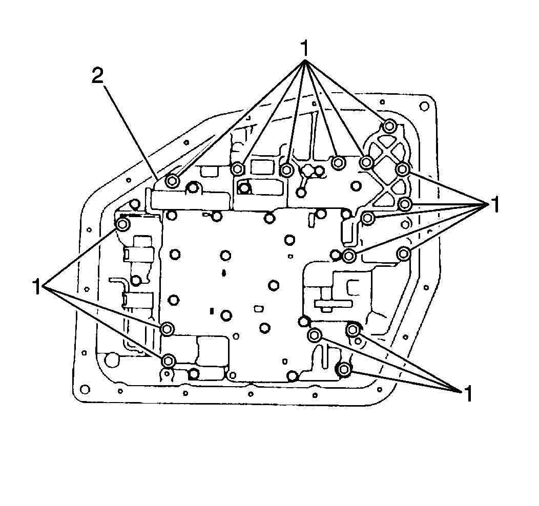
- Remove 22 bolts (1) and the valve body assembly (2) from the transaxle case (while disconnecting the manual valve link).
- Remove one bolt and the manual detent spring (1) from the transaxle case (2).
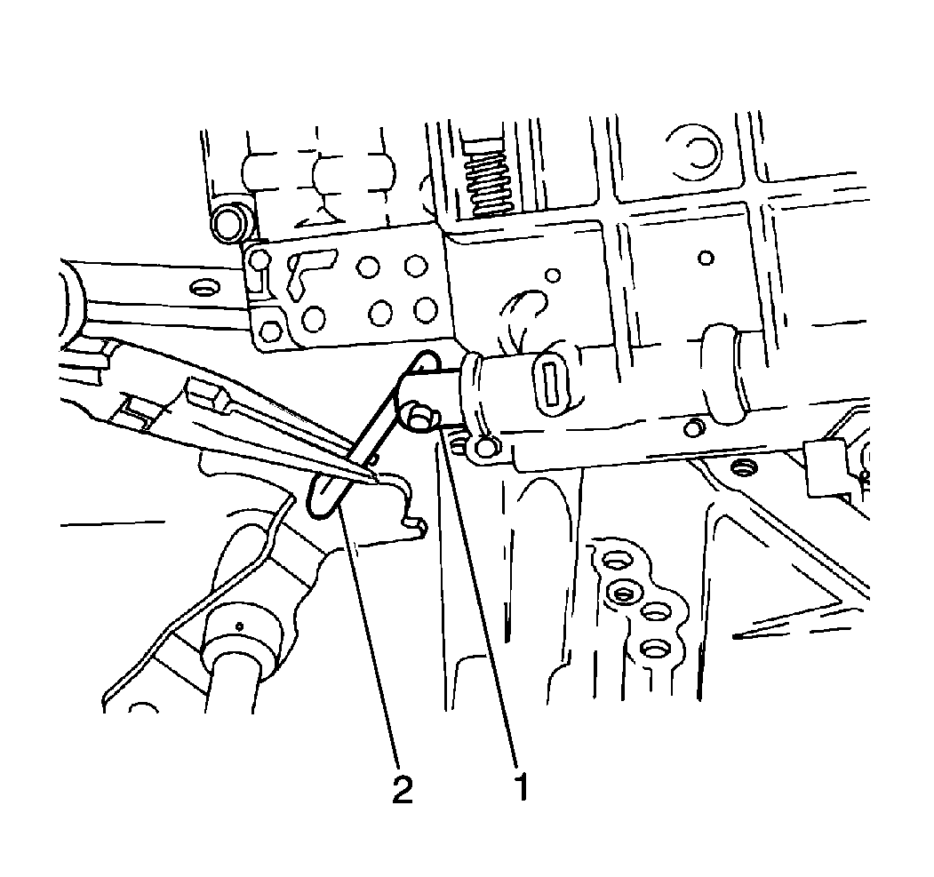
- Disconnect the manual valve link (2) from the manual detent lever.
- Remove the check ball body (1) and spring (3) from the transaxle case (2).
- Remove the intermediate brake apply seal (1) from the transaxle case.
- Remove the intermediate brake apply tube (1) from the transaxle case.
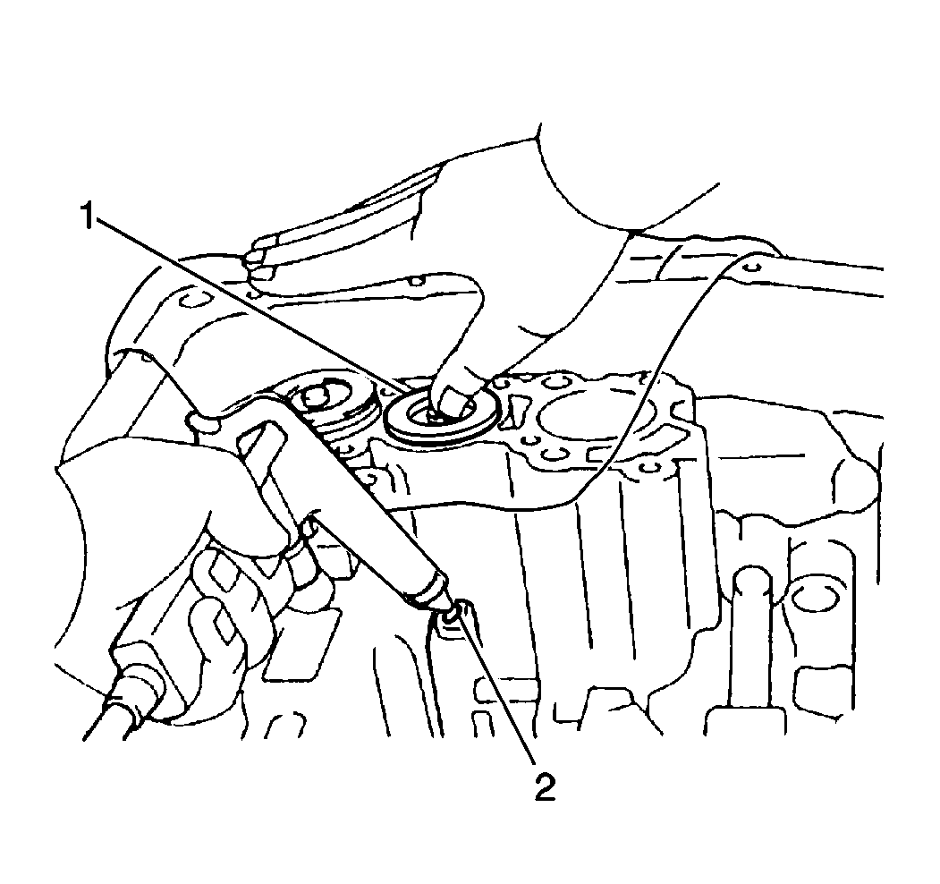
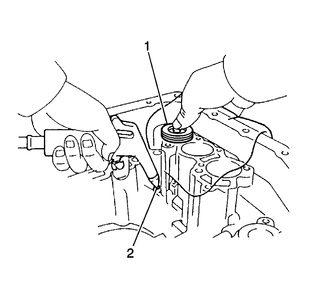
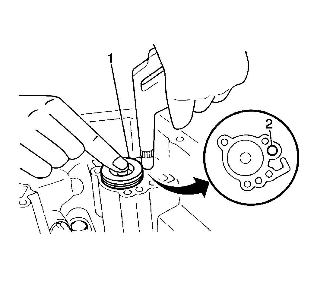
- Remove the B2 accumulator piston (1) and spring from the transaxle case by slowly applying low pressure compressed air into the fluid passage (2).
- Remove the two seals from the B2 accumulator piston.
- Remove the C2 accumulator piston (1) and spring from the transaxle case by slowly applying low pressure compressed air into the fluid passage (2).
- Remove the two seals from the C2 accumulator piston.
- Remove the C1 accumulator piston (1) and spring from the transaxle case by slowly applying low pressure compressed air into the fluid passage (2).
- Remove the one seal from the C1 accumulator piston.
- Remove the C3 accumulator piston (1) and the spring from the transaxle case by slowly applying low pressure compressed air into the fluid passage (2).
- Remove two seals from the C3 accumulator piston.
- Remove the following components from the transaxle case:
- Use a hammer and chisel in order to remove the manual lever hub protection sleeve (1) from the manual detent lever hub.
- Use a standard drift punch and hammer in order to remove one roll pin from the manual detent lever hub (1).
- Remove the retaining spring (2) from the manual shaft (1).
- Remove the following components from the transaxle case:
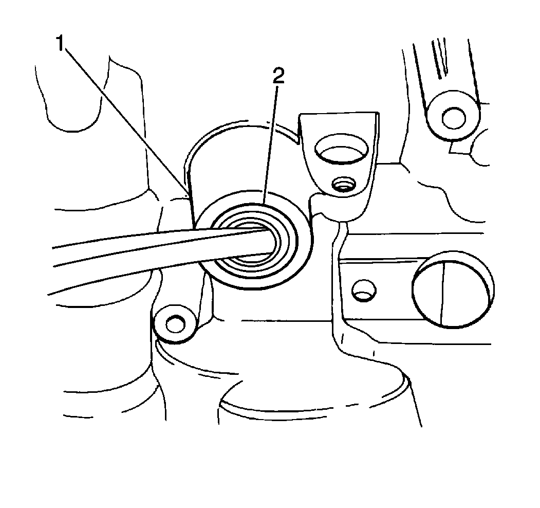
- Remove the manual shaft fluid seal (2) from the transaxle case (1).
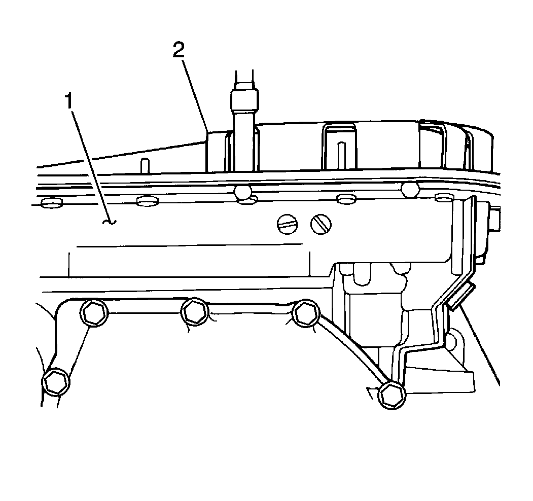
| • | 18 bolts |
| • | The transaxle fluid pan (2) |
| • | The gasket |
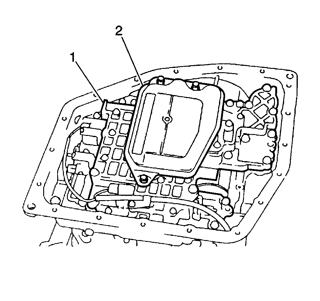
| • | Three bolts |
| • | The fluid filter screen (2) |
| • | The gasket |
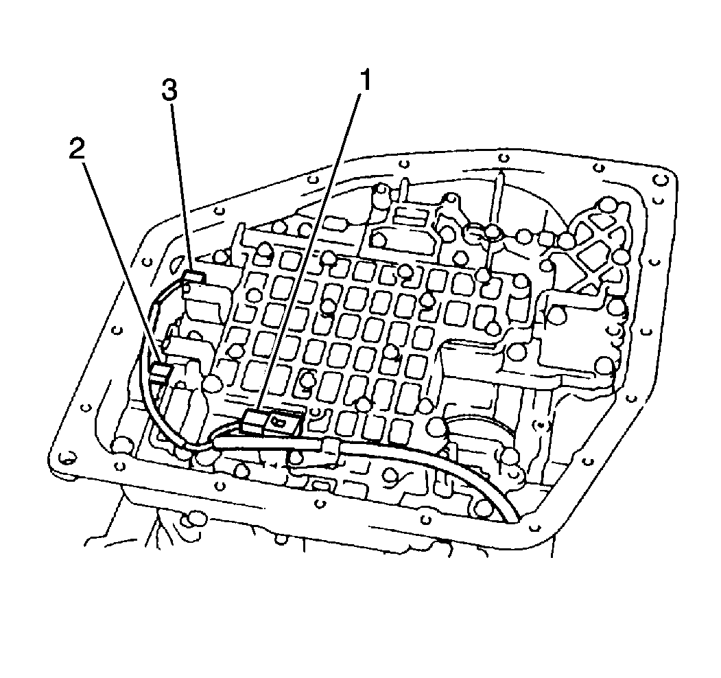
| • | Shift solenoid No. 1 (3) |
| • | Shift solenoid No. 2 (2) |
| • | The torque converter clutch (TCC) solenoid |
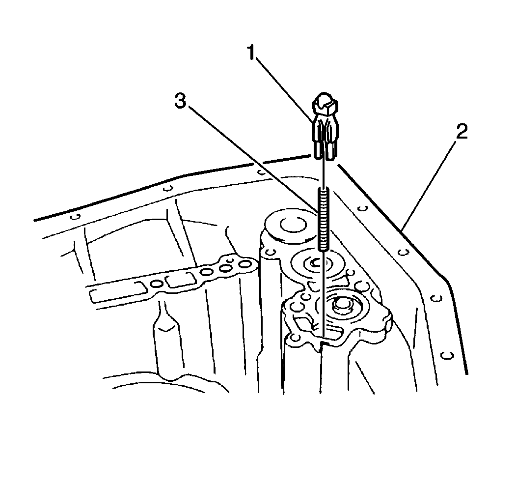
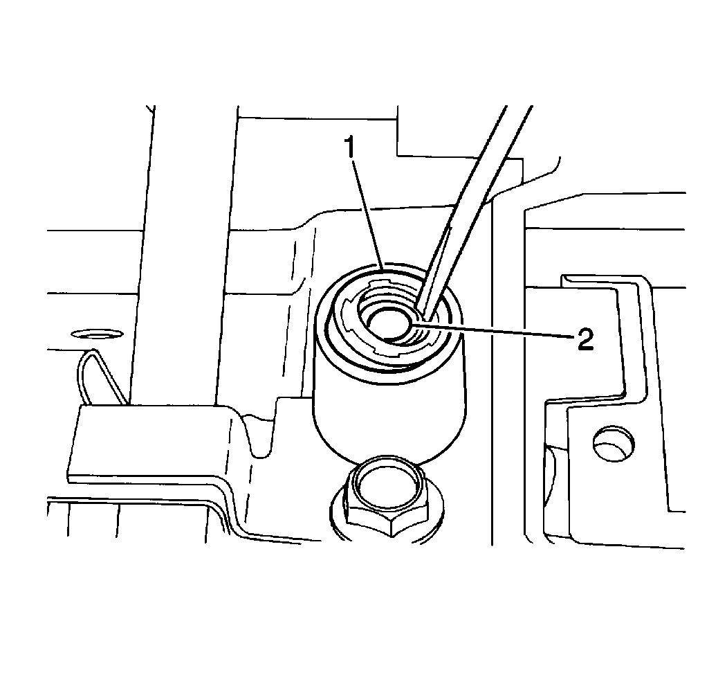
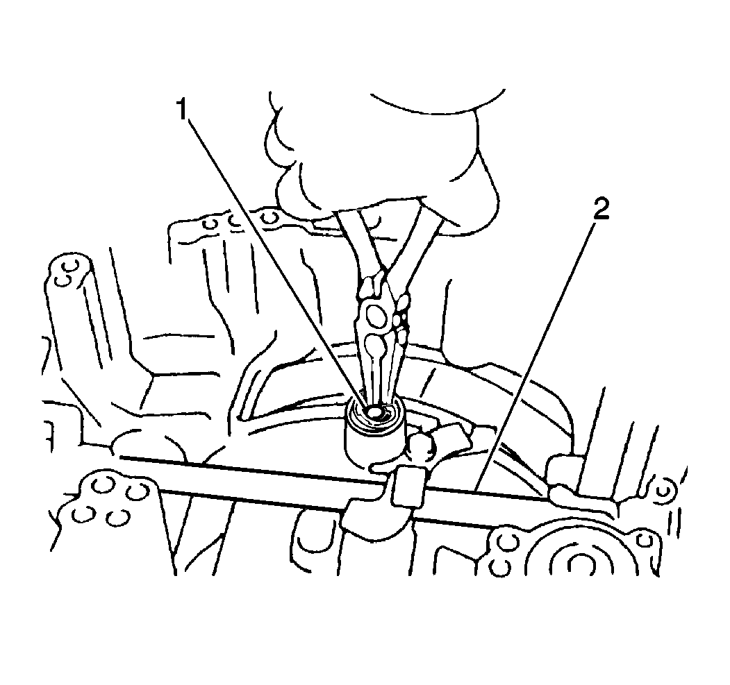
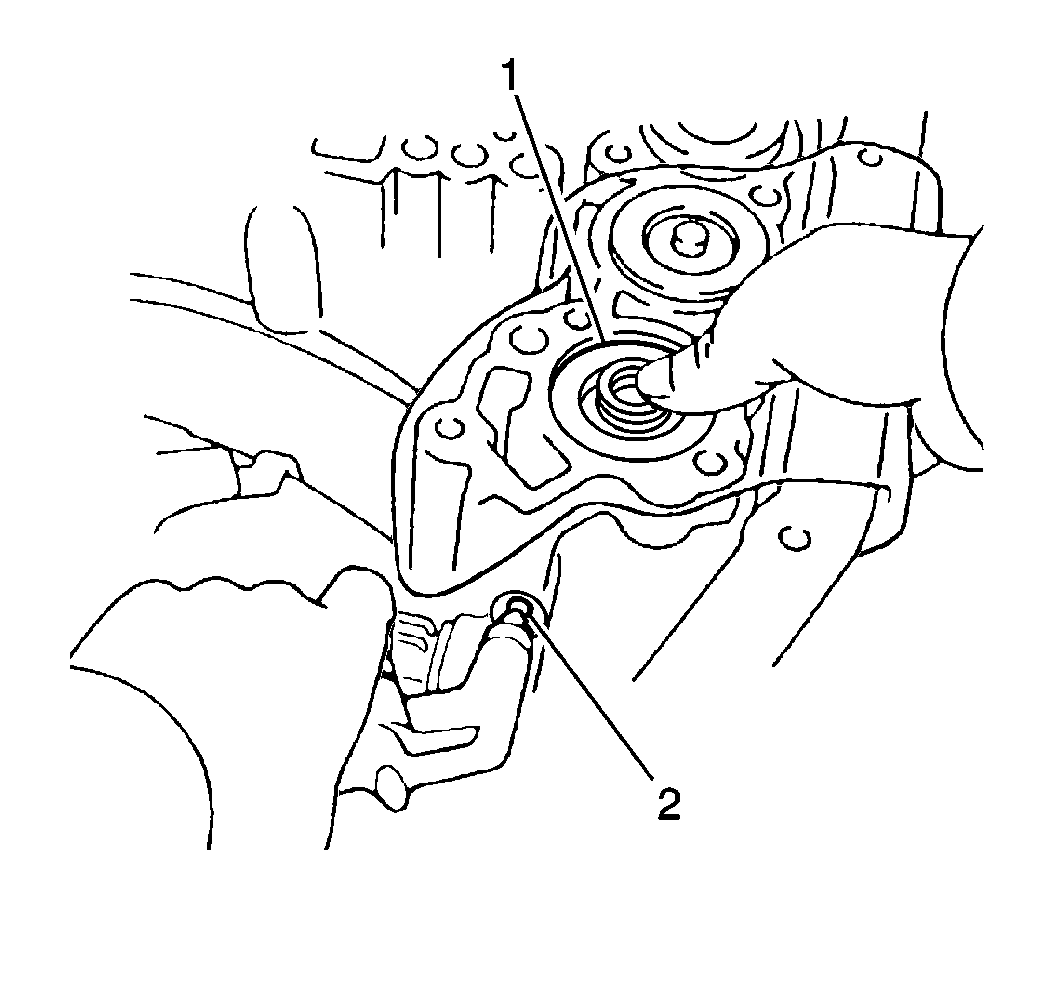
Important: When using compressed air to remove components, air pressure should not exceed 98 kPa (14 psi).
| • | One bolt |
| • | The second coast brake band guide (1) |
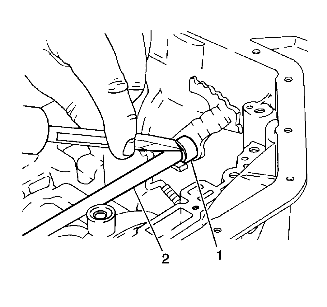
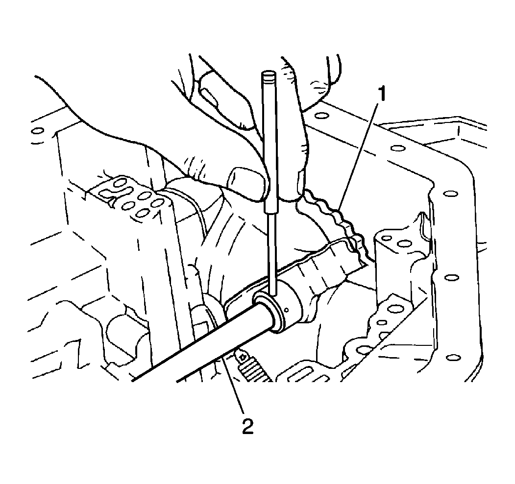
Important: Do NOT drop the roll pin into the transaxle case.
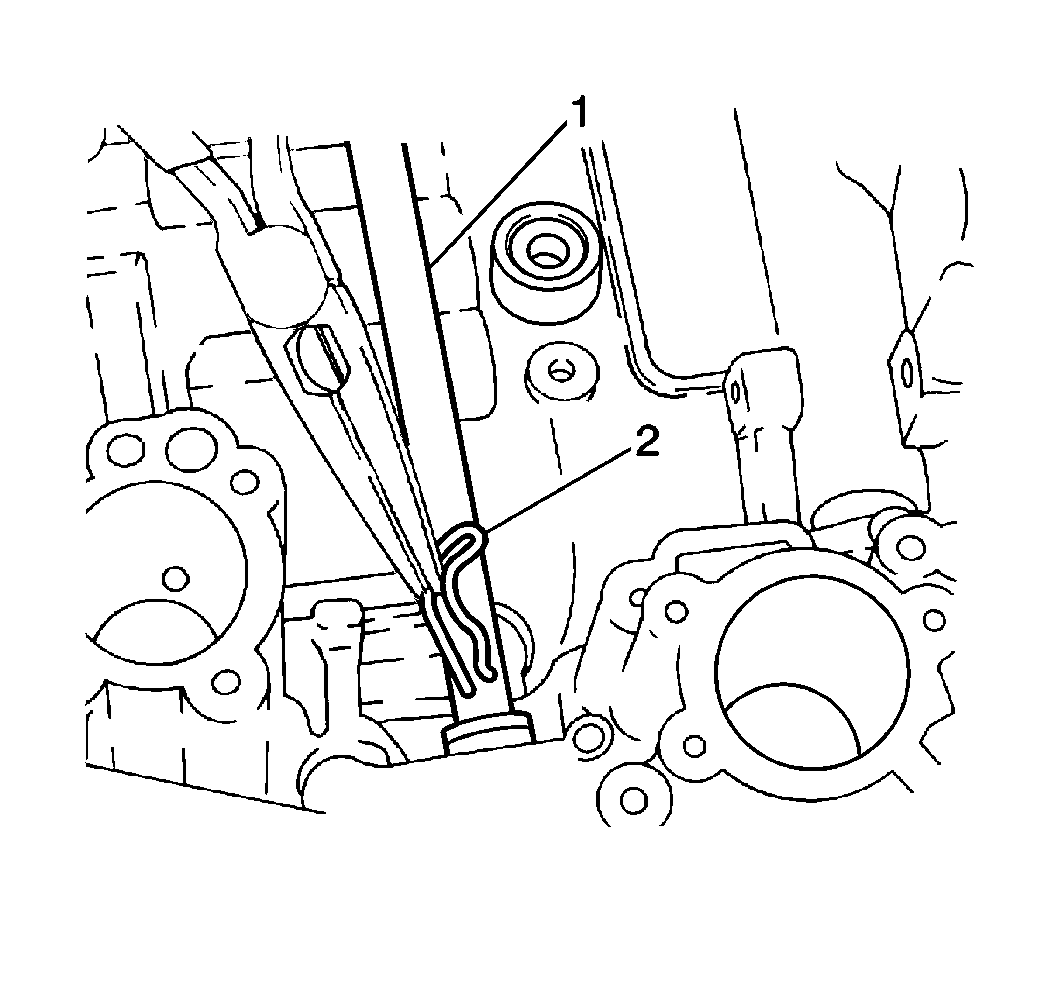
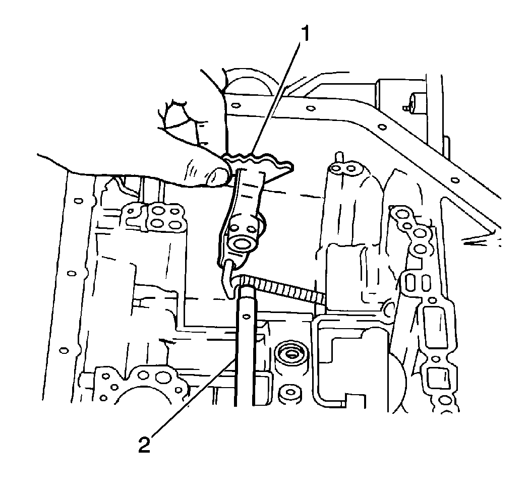
| • | The manual shaft (2) |
| • | The manual detent lever (1) and washer |
