Tools Required
| • | J 7872 Magnetic
Base Indicator Set |
| • | J 36850 Transjel®
Transmission Assembly Lubricant |
Removal Procedure
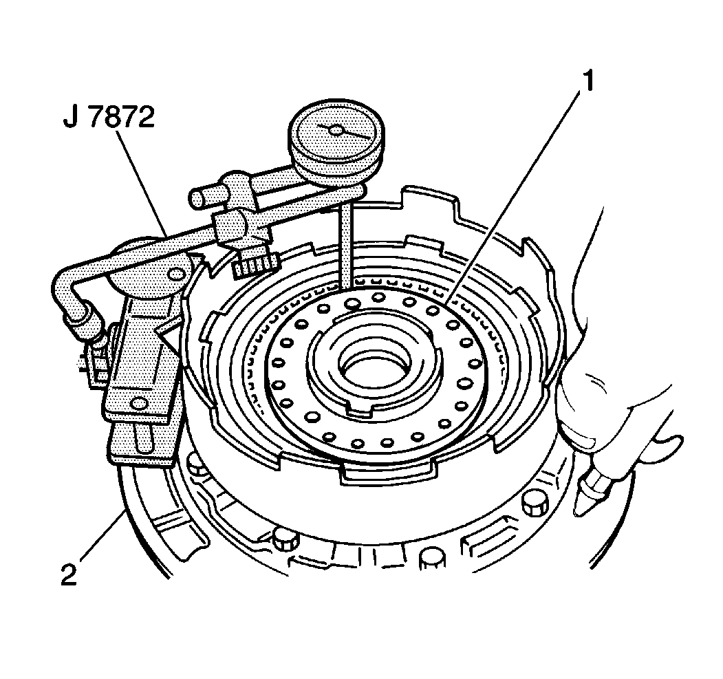
- Use a J 7872
in order to measure the direct clutch
piston stroke before disassembly.
| 1.1. | Temporarily install the direct clutch assembly onto the fluid
pump (2) and place the J 7872
plunger on the direct clutch piston (1). |
| 1.2. | Apply 392-785 kPa (57-114 psi) of compressed
air into the direct clutch apply passage of the fluid pump and observe the
J 7872
. |
| 1.3. | The standard direct clutch piston stroke is greater or less than
specified, inspect all direct clutch components for excessive wear. |
| 1.4. | Standard direct clutch piston stroke 1.12-1.52 mm
(0.0441-0.0598 in). |
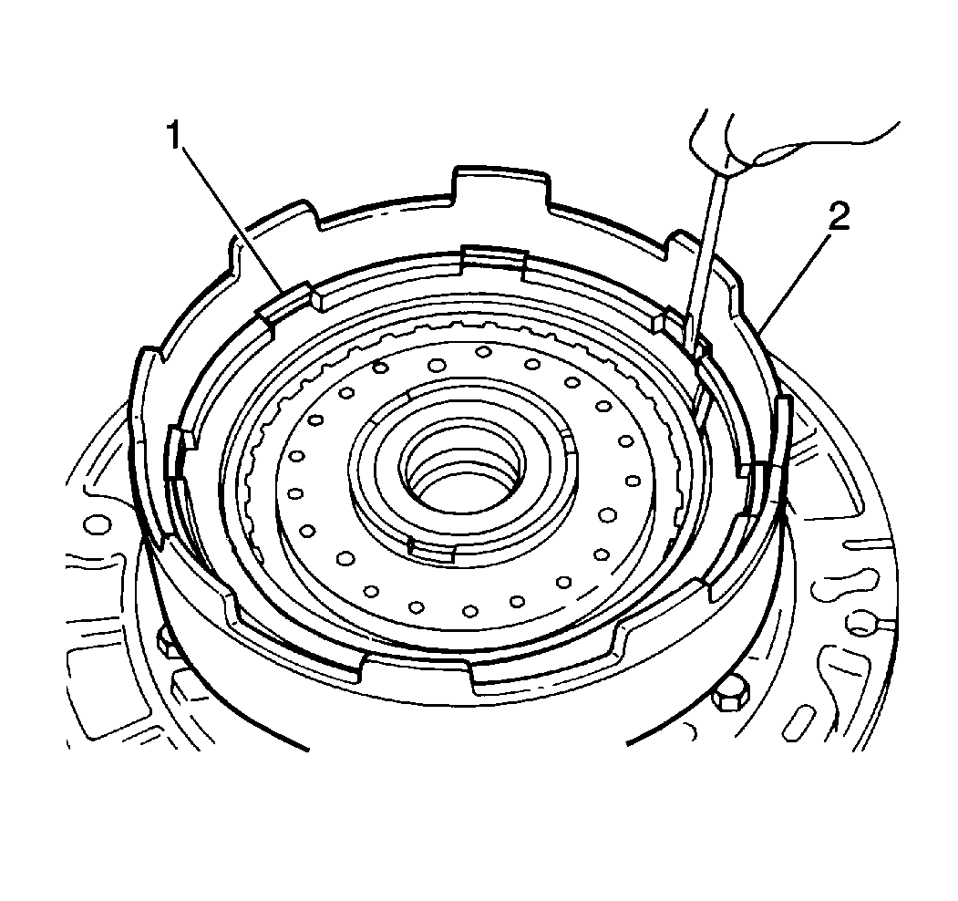
- Remove the direct clutch
snap ring (1) from the direct clutch drum (2).
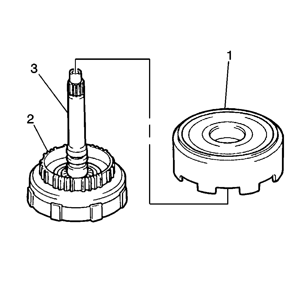
- Remove the direct clutch
assembly (1) from the forward clutch assembly (2).
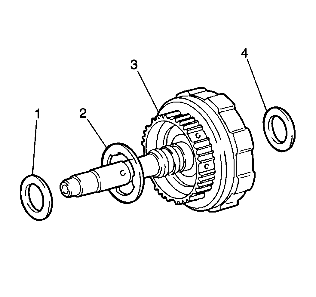
- Remove the forward clutch
inner thrust bearing (4) from the center of the forward clutch drum.
- Remove the direct clutch thrust washer (2) from the top
of the forward clutch assembly (3).
- Remove the forward clutch outer thrust bearing (1) from
the top of the forward clutch drum.
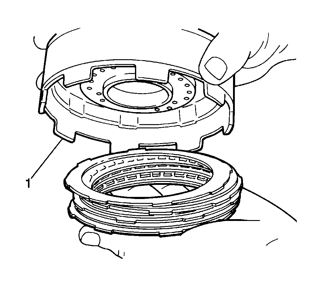
- Remove the following components
from the direct clutch drum (1):
| • | The direct clutch flange |
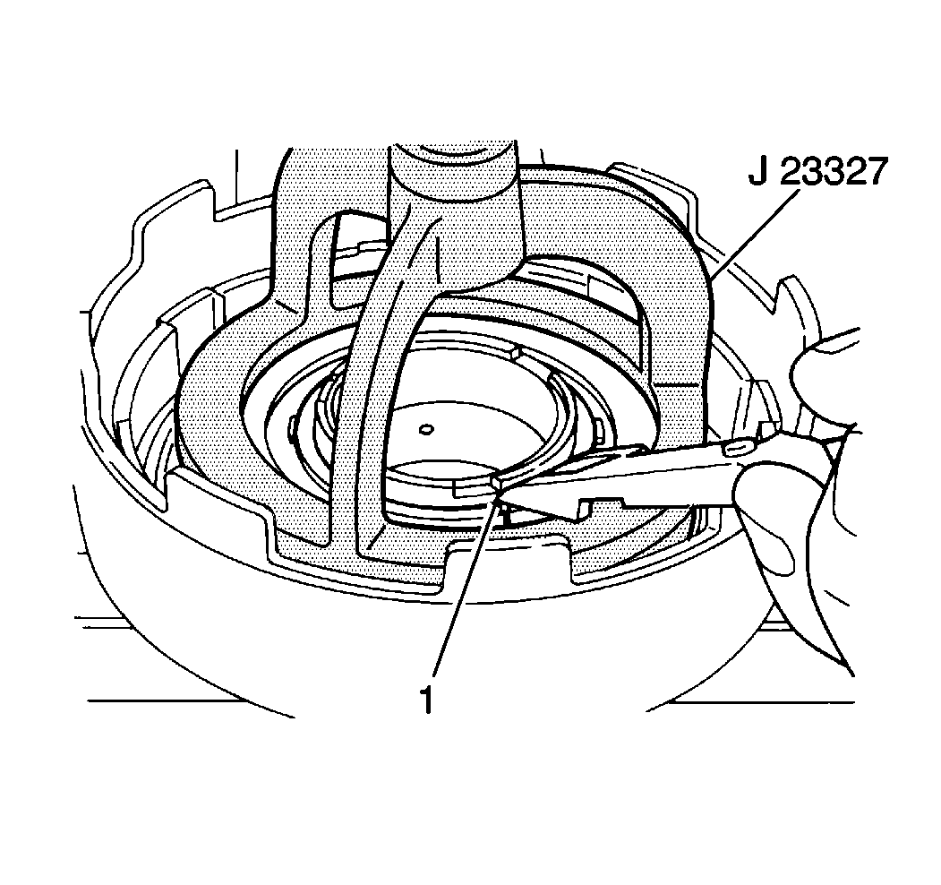
- Use a J 23327
and a hydraulic press in order to
remove the direct clutch piston return spring snap ring (1) from the direct
clutch piston return spring retainer.
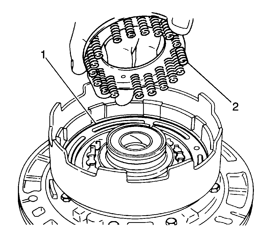
- Remove the direct clutch
piston return springs (2) from the direct clutch piston (1).
Notice: When using compressed air to remove components, air pressure should
not exceed 98 kPa (14 psi).
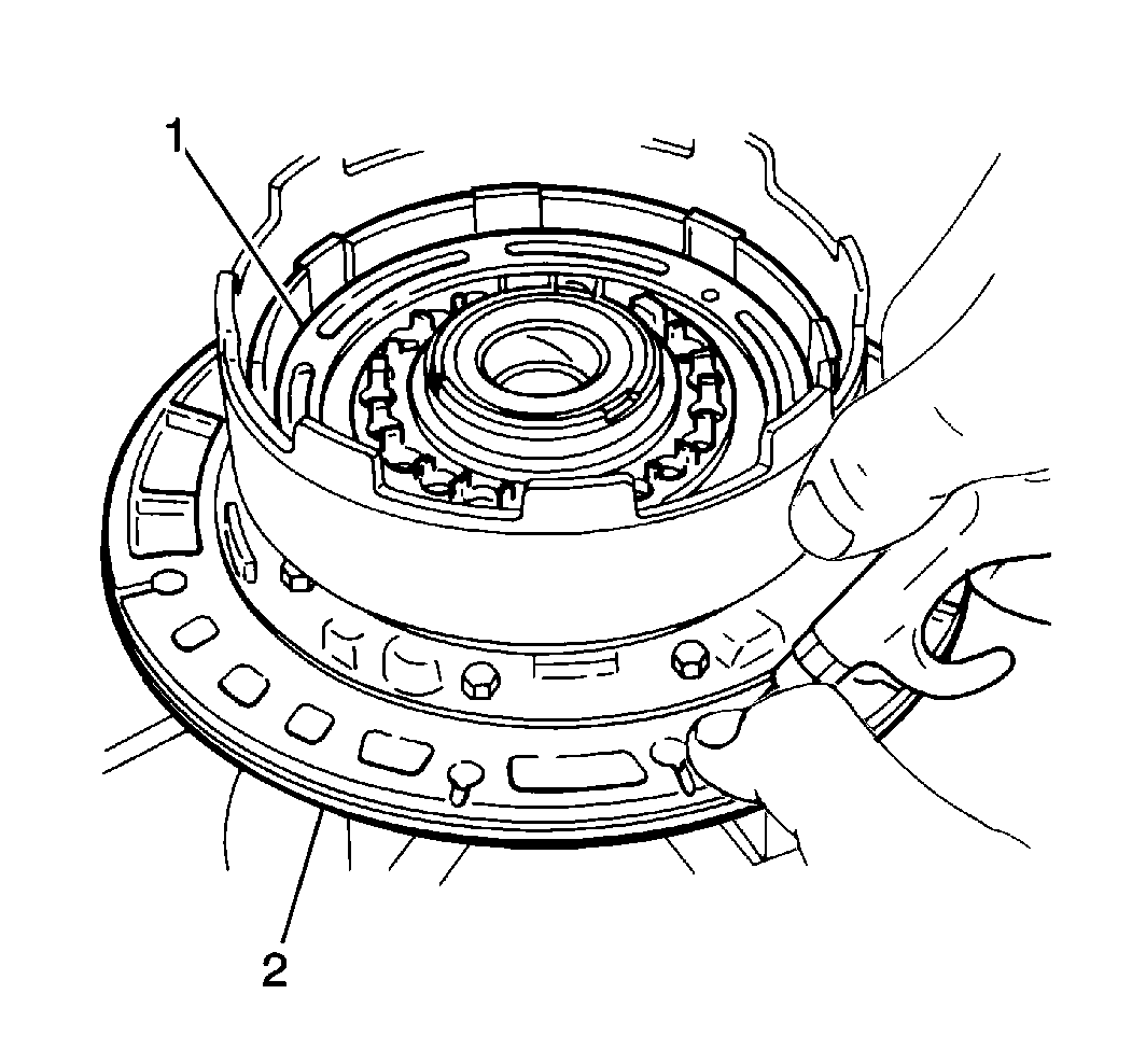
- Remove the direct clutch piston (1) from the direct clutch drum
by temporarily installing the direct clutch assembly onto the fluid pump (2).
Apply low pressure compressed air into the direct clutch apply passage
of the fluid pump.
- Remove the direct clutch piston seals from the direct clutch piston.
- Clean all the direct clutch components and dry the components
thoroughly.
- Inspect the direct clutch discs for excessive wear or damage.
Replace the components as necessary.
- Inspect the direct piston for cracks or porosity and replace as
necessary.
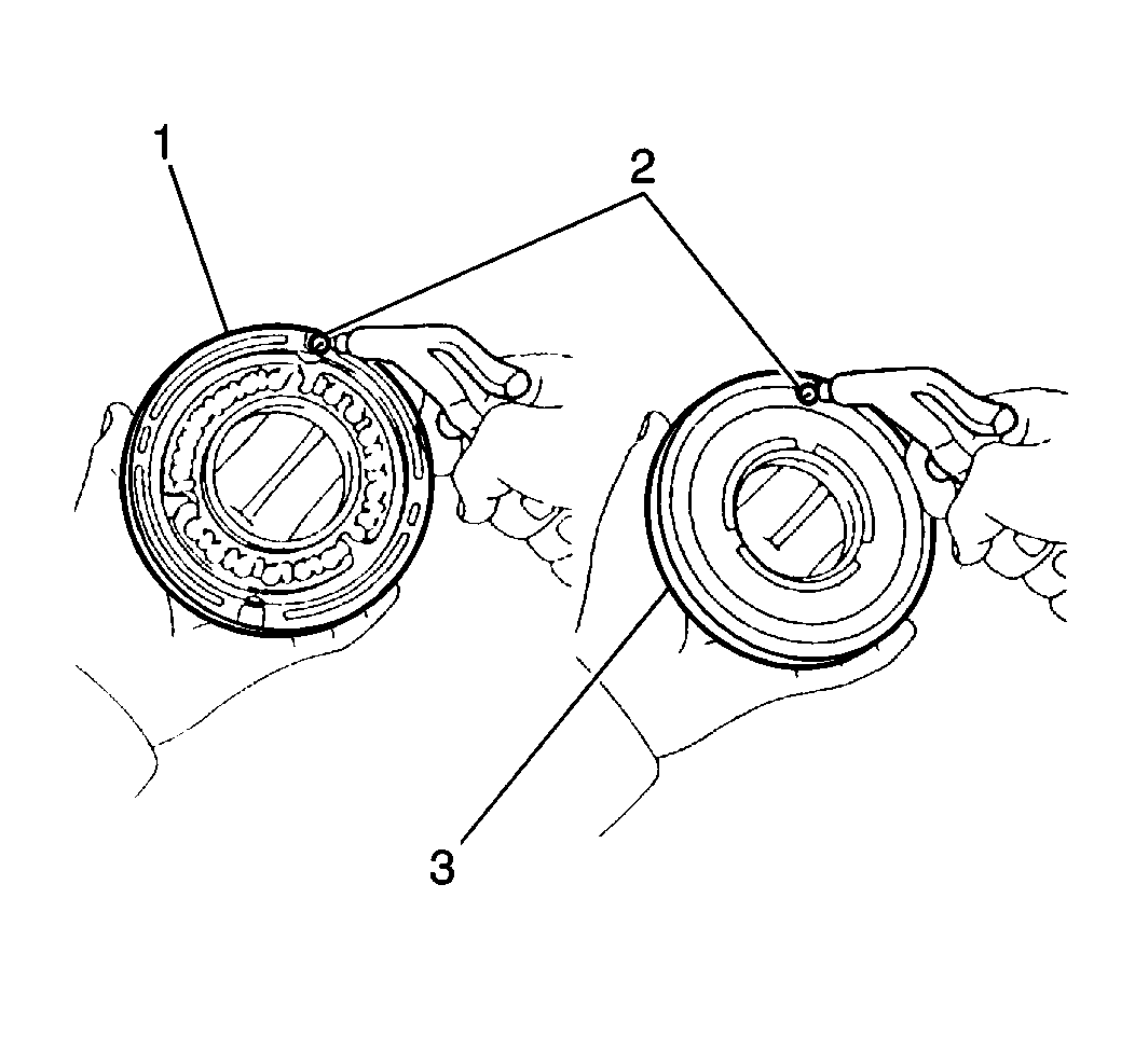
- Inspect the direct clutch
piston check ball (2) operation by applying compressed air into the working
and release sides of the direct clutch piston (1,3). There must be no
air leakage on the working side. Air must pass freely through the release
side. If these conditions do not exist, replace the direct clutch piston.
- Inspect the direct clutch piston return spring for distortion
or weakness and replace as necessary.
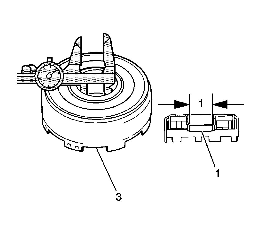
- Use the J 26900-6
in order to measure the inside diameter
of the direct clutch bushing (1).
| • | The maximum inside diameter of the direct clutch bushing is 48.270 mm
(1.9004 in) |
| • | If the inside diameter of the direct clutch house bushing is greater
than specified, replace the direct clutch drum |
Installation Procedure
Important: When installing new clutch discs in the 1st-reverse brake, the underdrive
brake, the underdrive clutch, the intermediate brake, the forward clutch or
the direct clutch assemblies, the new clutch discs MUST be soaked in Dexron®-III
Automatic Transmission Fluid GM P/N 12346143 or equivalent, two hours prior
to installation. This causes the clutch material on the discs to permeate
with fluid which will aid in ease of assembly and prevent clutch overheating
on first time engagement.
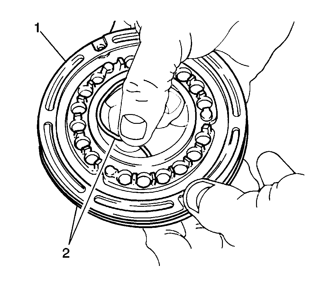
- Install two new direct
clutch piston seals (2) onto the direct clutch piston (1).
- Apply J 36850
to the new direct clutch piston seals.
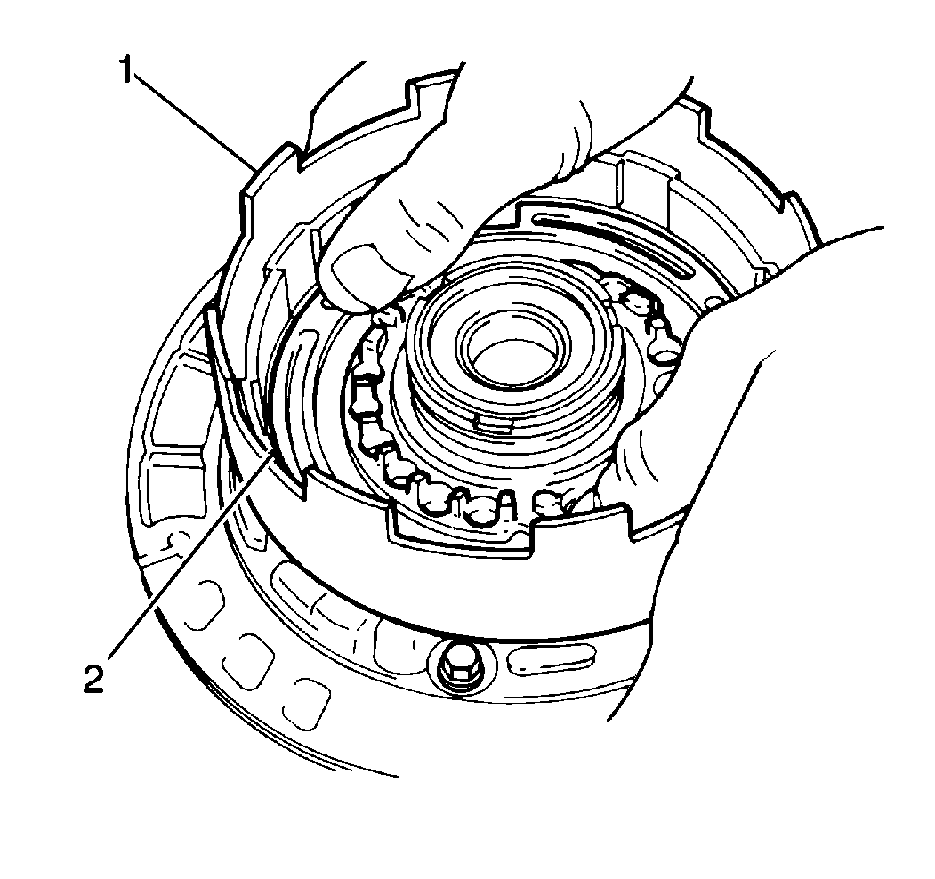
- Install the direct clutch
piston (2) into the direct clutch drum (1) with the cup side
facing upwards.
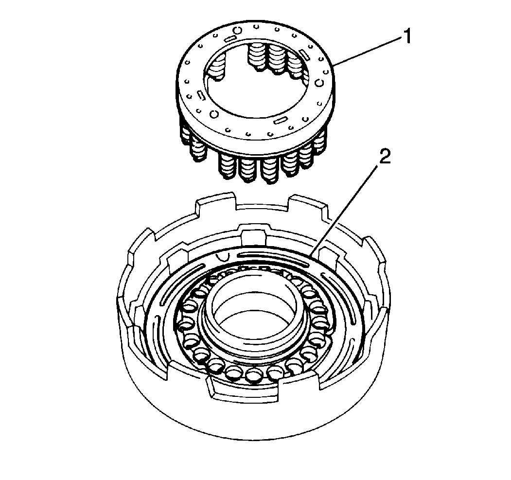
- Install the direct clutch
piston return springs (1) onto the direct clutch piston (2).
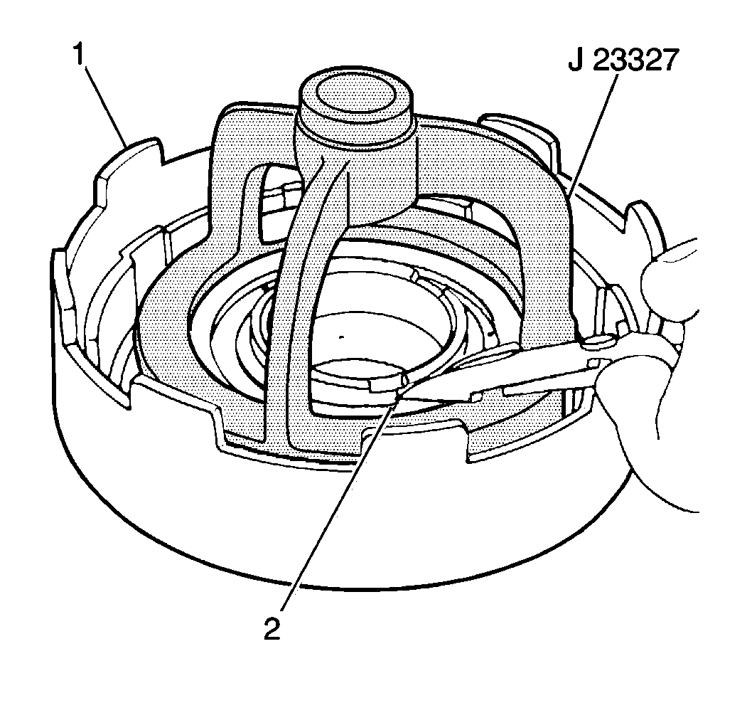
- Use a J 23327
and a hydraulic press to install the
direct clutch piston return spring snap ring (2) onto the direct
clutch piston return spring retainer.
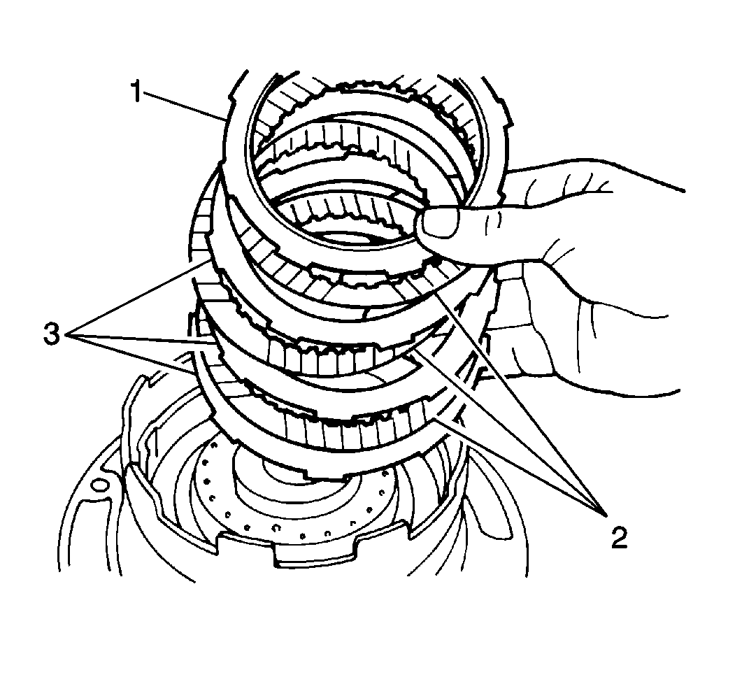
Important: The direct clutch flange must be installed with the flat side facing
down and the stepped portion facing upwards.
- Install three discs (2), 3 plates (3) and the direct
clutch flange (1) into the direct clutch drum in the following order:
- Install the direct clutch snap ring into the direct clutch drum.

- Use a J 7872
in order to measure the direct clutch
piston stroke after assembly is complete.
| 8.1. | Temporarily install the direct clutch assembly (1) onto
the fluid pump (2) and place the J 7872
on the direct clutch piston. |
| 8.2. | Apply 392-785 kPa (57-114 psi) of compressed
air into the direct clutch apply passage of the fluid pump and observe the
J 7872
. |
| 8.3. | The standard direct clutch piston stroke should fall within 1.12-1.52 mm
(0.0441-0.0598 in). |
| 8.4. | If the direct clutch piston stroke is greater or less than specified,
and all direct clutch components exhibit little or no wear, select one of
the following direct clutch flange sizes to bring the direct clutch piston
stroke within specification: |


