Tools Required
J 36850 Transjel® Transmission Assembly Lubricant
- Apply the J 36850 (2) to the new manual shaft fluid seal lip.
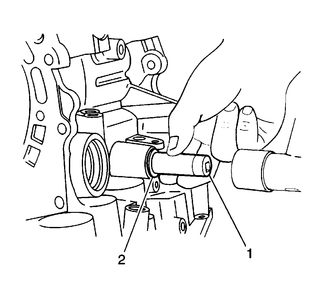
- Install the new manual shaft fluid seal (2) into the transaxle case using a 14 mm socket (1) and a hammer.
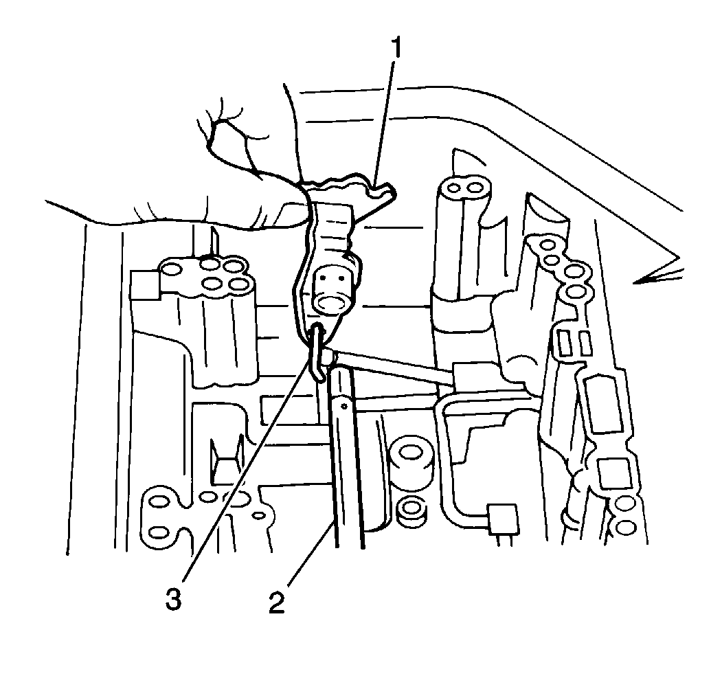
- Install the manual detent lever (1), the washer and the manual shaft (2) into the transaxle case. Secure with one retaining spring.
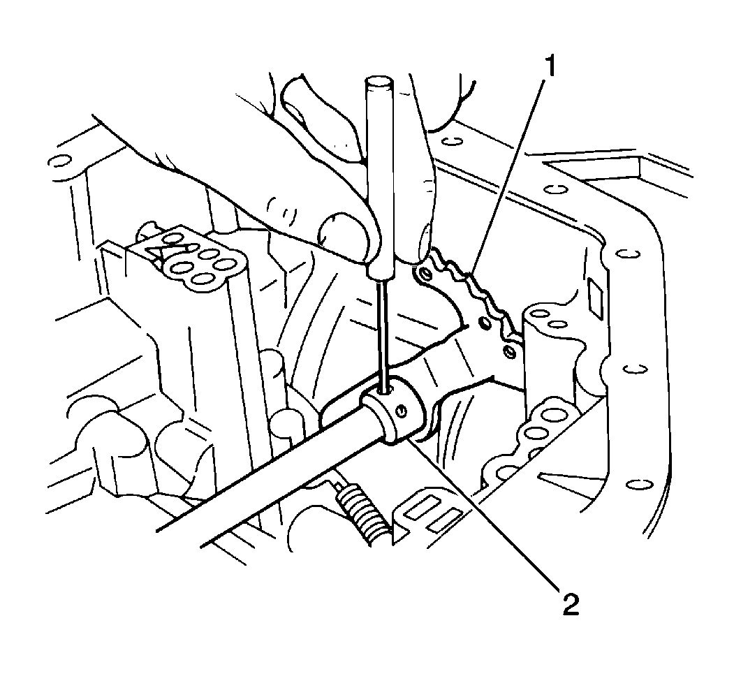
- Install the roll pin manual detent lever (2) using a standard drift punch and a hammer.
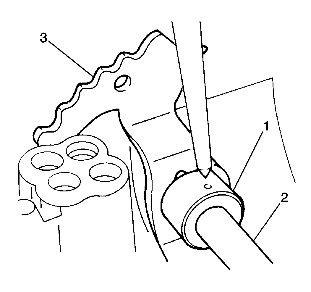
- Slide the protection sleeve onto the manual detent lever hub to cover the roll pin.
- Stake the protection sleeve (1) to the manual lever hub (2).
- Install the two new C3 accumulator piston seals onto the C3 accumulator piston.
- Apply J 36850 to the two new C3 accumulator piston seals.
- Install the C3 accumulator piston and spring into the transaxle case.
- Install the one new C1 accumulator piston seal onto the C1 accumulator piston.
- Apply J 36850 to the new C1 accumulator piston seal.
- Install the C1 accumulator piston and the spring into the transaxle case.
- Install two new C2 accumulator piston seals onto the C2 accumulator piston.
- Apply J 36850 to the new C2 accumulator piston seals.
- Install the C2 accumulator piston spring into the transaxle case.
- Install the two new B2 accumulator piston seals onto the B2 accumulator piston.
- Apply J 36850 to the two new B2 accumulator piston seals.
- Install the B2 accumulator piston and the spring into the transaxle.
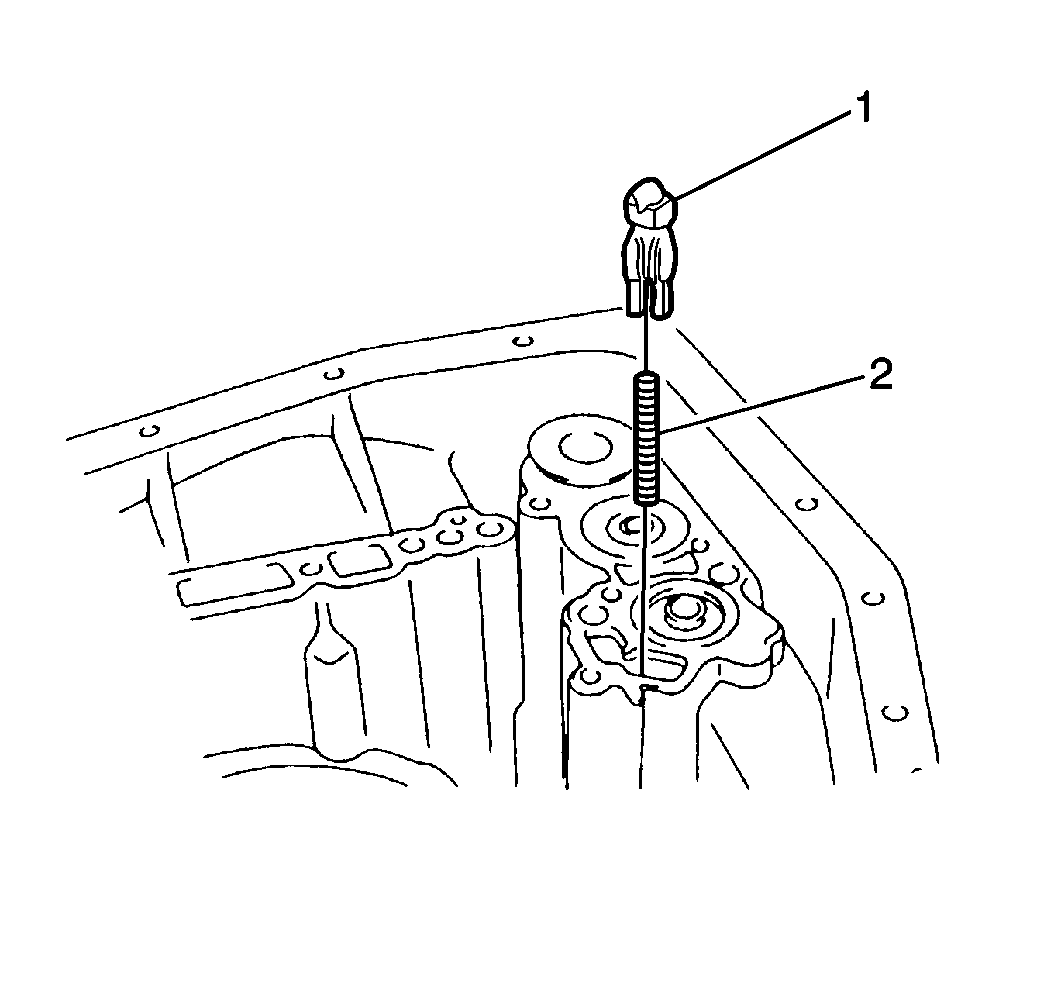
- Install the intermediate brake apply tube (2) into the transaxle case.
- Install the intermediate brake apply seal (1) into the transaxle case.
- Install the check the ball body (1) and the spring (2) into the transaxle case.
- Install the valve body assembly onto the transaxle case while simultaneously connecting the manual valve link to the manual detent lever. Secure the assemblies with 22 bolts.
- Inspect the TV cable O-ring for cuts or other damage. Replace the O-rings as necessary.
- Apply J 36850 to the TV cable O-ring.
- Install the TV cable into the transaxle case and the throttle valve cam.
- Inspect the solenoid wire harness O-ring for cuts or other damage. Replace the O-rings as necessary.
- Apply J 36850 to the solenoid wire harness O-ring.
- Install the solenoid wire harness into the transaxle case.
- Install the solenoid wire harness clip onto the valve body assembly. Secure the solenoid with 1 bolt.
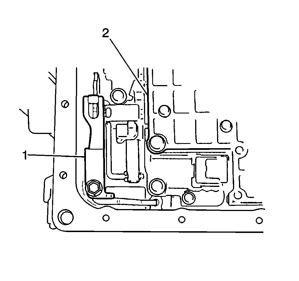
- Install the manual detent spring (1) into the transaxle case. Secure the spring with one bolt.
- Install the electrical connectors onto the shift solenoids No. 1 and No. 2 and the TCC solenoid.
- Clean the fluid filter screen and dry the screen thoroughly.
- Inspect the fluid filter screen mesh for tears or other damage. Replace the screen as necessary.
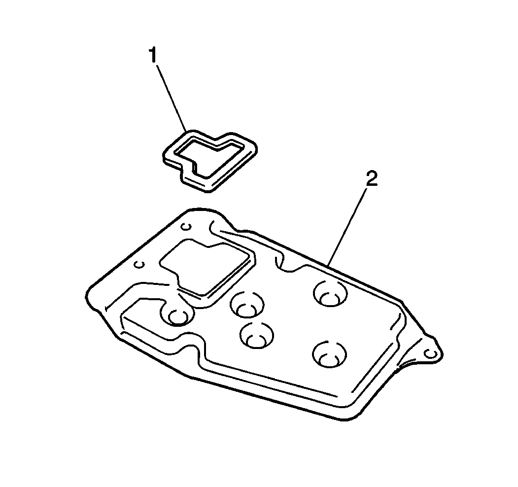
- Install the new fluid filter screen gasket (1) and the fluid filter screen (2) onto the valve body assembly. Secure the assembly with three bolts.
- Clean the transaxle fluid pan and the magnets thoroughly.
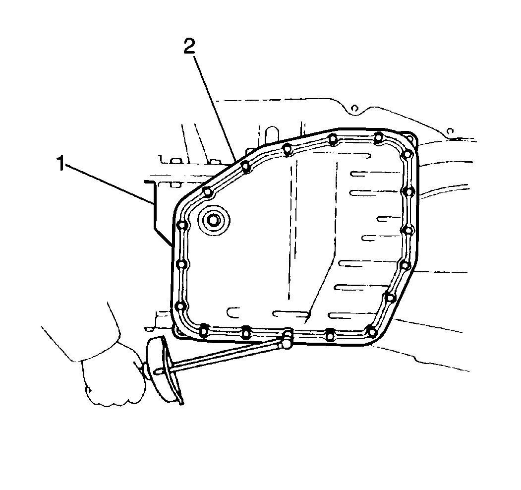
- Install the new transaxle fluid pan gasket and the transaxle fluid pan (2) onto the transaxle case (1). Secure the assembly with eighteen bolts.
- Install the solenoid wire harness retaining bolt (3) into the solenoid wire harness (2).
- Install the TV cable retaining bolt (4) into the TV cable (1).
- Install two new fluid cooler pipe union O-rings and the fluid cooler pipe unions (1) into the transaxle case.
- Install the PNP switch (1) onto the manual shaft (2) and secure with two bolts. Do not tighten the bolts fully.
- Install the manual shaft lock plate and the nut onto the PNP switch.
- Stake the lock plate behind the manual shaft nut.
- Adjust the PNP switch. Refer to Park/Neutral Position Switch .
- Install the manual lever (1) onto the manual shaft and secure with one washer and 1 nut (2).
- Remove the J 37268 with the transaxle assembly from the J 3289-20 .
- Remove the J 37268 from the transaxle case.
- Install the vent hose onto the vent elbow at the top of the transaxle case and secure with 1 clamp.
- Inspect the fluid filler tube O-ring for cuts or other damage. Replace the O-rings as necessary.
- Apply J 36850 to the fluid filler tube O-ring.
- Install the fluid filler tube into the transaxle case and secure the tube with 1 bolt.
- Install the fluid level indicator from the fluid filler tube.
- Install 1 bolt, the fluid cooler pipe bracket, and the inlet and outlet fluid cooler pipes to the transaxle case. Secure the components with 1 bolt.
- Install the shift select cable bracket from the transaxle case and secure with 2 bolts.
- Install the rear transaxle mount to the torque converter housing and secure with 2 bolts.
- Connect the front transaxle mount to the torque converter housing and secure with 2 bolts.
- Install the left transaxle mounting bracket onto the top of the transaxle case and secure with 3 bolts.
- Install the torque converter onto the input shaft.

Important: When installing the intermediate brake apply tube, verify that the flexible end of the intermediate brake apply tube is inserted toward the intermediate brake drum (toward the inside of the transaxle).
Notice: Use the correct fastener in the correct location. Replacement fasteners must be the correct part number for that application. Fasteners requiring replacement or fasteners requiring the use of thread locking compound or sealant are identified in the service procedure. Do not use paints, lubricants, or corrosion inhibitors on fasteners or fastener joint surfaces unless specified. These coatings affect fastener torque and joint clamping force and may damage the fastener. Use the correct tightening sequence and specifications when installing fasteners in order to avoid damage to parts and systems.
Tighten
Tighten the valve body assembly bolts to 10 N·m (89 lb in).
Tighten
Tighten the solenoid wire harness clip bolt to 6 N·m (53 lb in).
Tighten
Tighten the manual detent spring bolt to 10 N·m (89 lb in).
Tighten
Tighten the fluid filter screen bolts to 10 N·m (89 lb in).
Tighten
Tighten transaxle fluid pan bolts to 5 N·m (44 lb in).
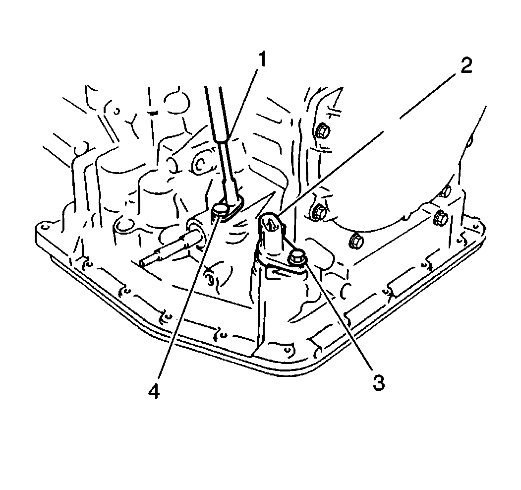
Tighten
Tighten the solenoid wire harness retaining bolt to 5 N·m
(44 lb in).
Tighten
Tighten the TV cable retaining bolt to 5 N·m (44 lb in).

Tighten
Tighten the fluid cooler pipe unions to 29 N·m (21 lb ft).

Tighten
Tighten the manual shaft nut to 12 N·m (106 lb in).
Tighten
Tighten the PNP switch mounting bolts to 5 N·m (44 lb in).
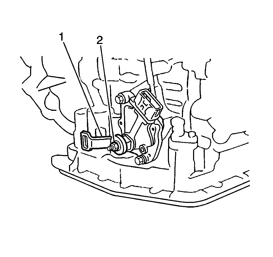
Tighten
Tighten the manual lever nut to 13 N·m (115 lb in).
Tighten
Tighten the fluid filler tube bracket bolt to 5 N·m (44 lb in).
Tighten
| • | Tighten the fluid cooler pipe bracket bolt to 5 N·m (44 lb in). |
| • | Tighten the inlet and outlet fluid cooler pipe fittings to 34 N·m (25 lb ft). |
Tighten
Tighten the shift select cable bracket bolts to 5 N·m (44 lb in).
Tighten
Tighten the rear transaxle mounting bracket bolts to 23 N·m
(17 lb ft).
Tighten
Tighten the front transaxle mounting bracket bolts to 23 N·m
(17 lb ft).
Tighten
Tighten the left transaxle mounting bracket bolts to 23 N·m
(17 lb ft).
