For 1990-2009 cars only
Tools Required
J 26900-6 Dial Caliper
Removal Procedure
- Inspect the intermediate one-way clutch before disassembly by placing the intermediate brake hub and the intermediate one-way clutch onto the rear of the sun gear input drum, holding the sun gear input drum stationary and rotating the intermediate brake hub.
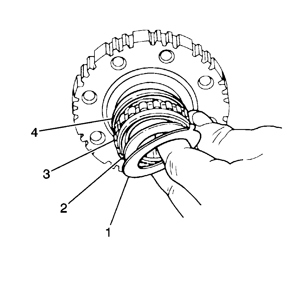
- Remove the rear thrust plate from the intermediate brake hub (1).
- Remove the intermediate one-way clutch retainers and the sprag assembly from the intermediate brake hub (4) .
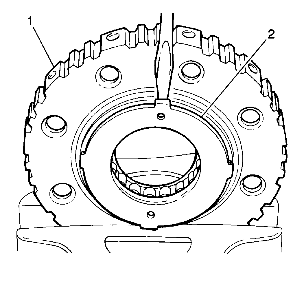
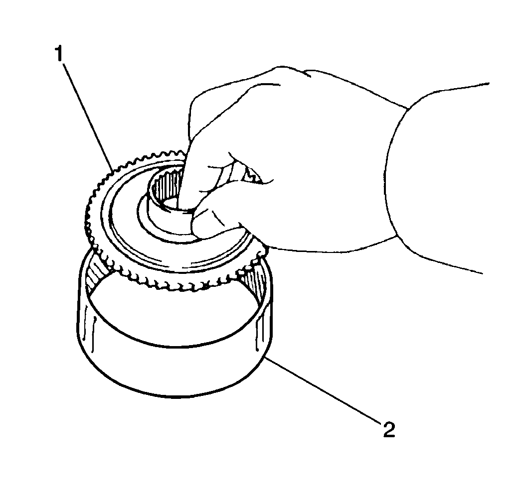
- Remove the front planetary ring gear flange snap ring (1) from the front planetary ring gear.
- Remove the front planetary ring gear flange (2) from the front planetary ring gear (1) .
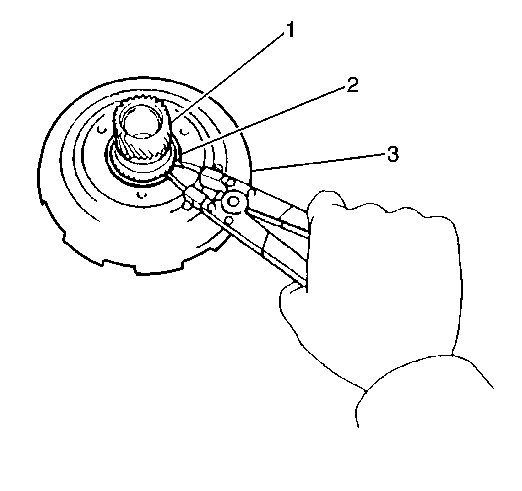
- Remove the sun gear input drum snap ring (2) from the sun gear at the rear of the sun gear input drum.
- Remove the sun gear (1) from the sun gear input drum (3).
- Remove the sun gear snap ring from the sun gear.
- Clean all components of the front planetary gearset and the sun gear input and dry these components thoroughly.
- Inspect the following components for excessive wear or damage. Replace the intermediate brake hub assembly as necessary:
- Inspect the following components for excessive wear or damage and replace as necessary:
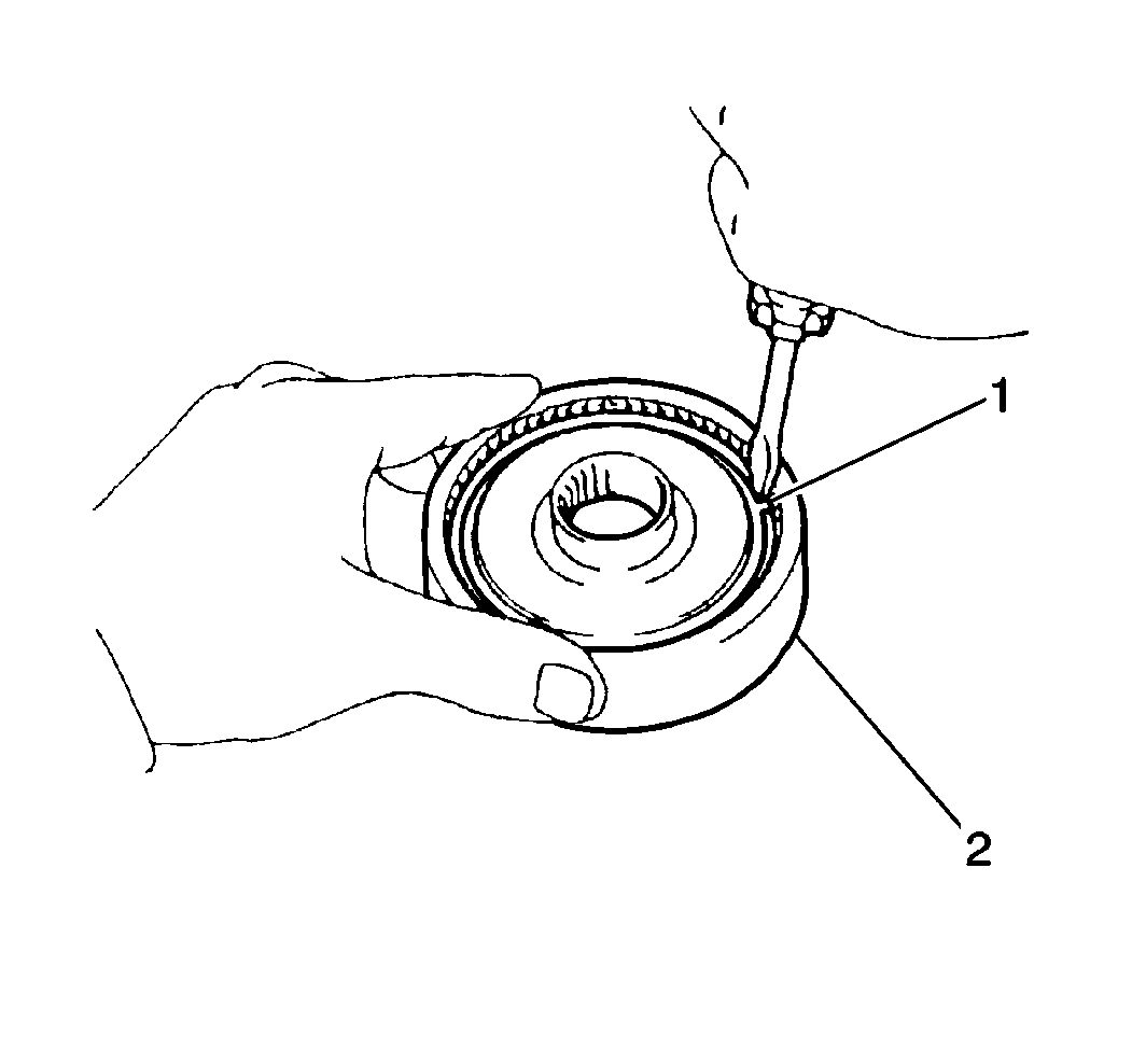
- Use a J 26900-6 in order to measure the front planetary ring gear flange bushing inside diameter (2).
- Use the J 26900-6 in order to measure the sun gear flange bushing inside diameter.
- Use a feeler gage (2) in order to measure the front planetary carrier pinion gear thrust clearance.
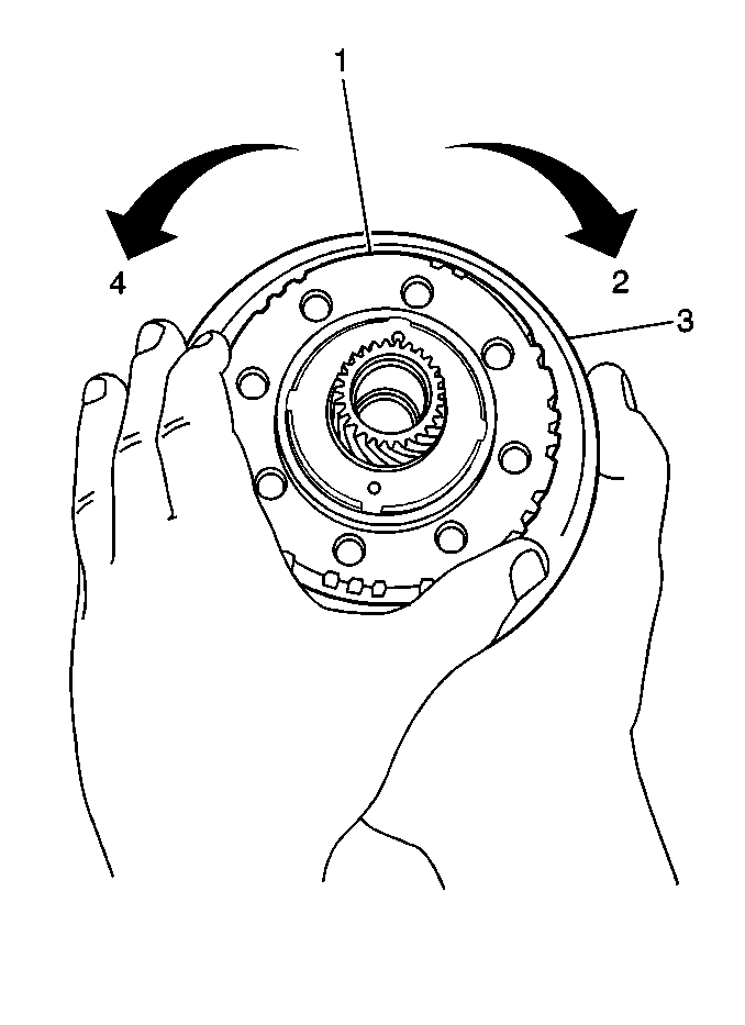
| • | The intermediate brake hub should turn freely in a clockwise direction (2) and should not turn in a counterclockwise direction (4). |
| • | If the intermediate brake hub is installed correctly on the sun gear input drum and the intermediate brake hub can be turned counterclockwise, replace the intermediate brake hub and intermediate one-way clutch |
Notice: The intermediate one-way clutch should be disassembled for inspection purposes only. If excessive wear or damage is found in any component of the intermediate one-way clutch upon inspection, replace the intermediate brake hub assembly.
| • | The intermediate one-way clutch outer race |
| • | The retainers |
| • | The sprag assembly |
| • | The front planetary ring gear |
| • | The front planetary carrier pinion gears |
| • | The sun gear |
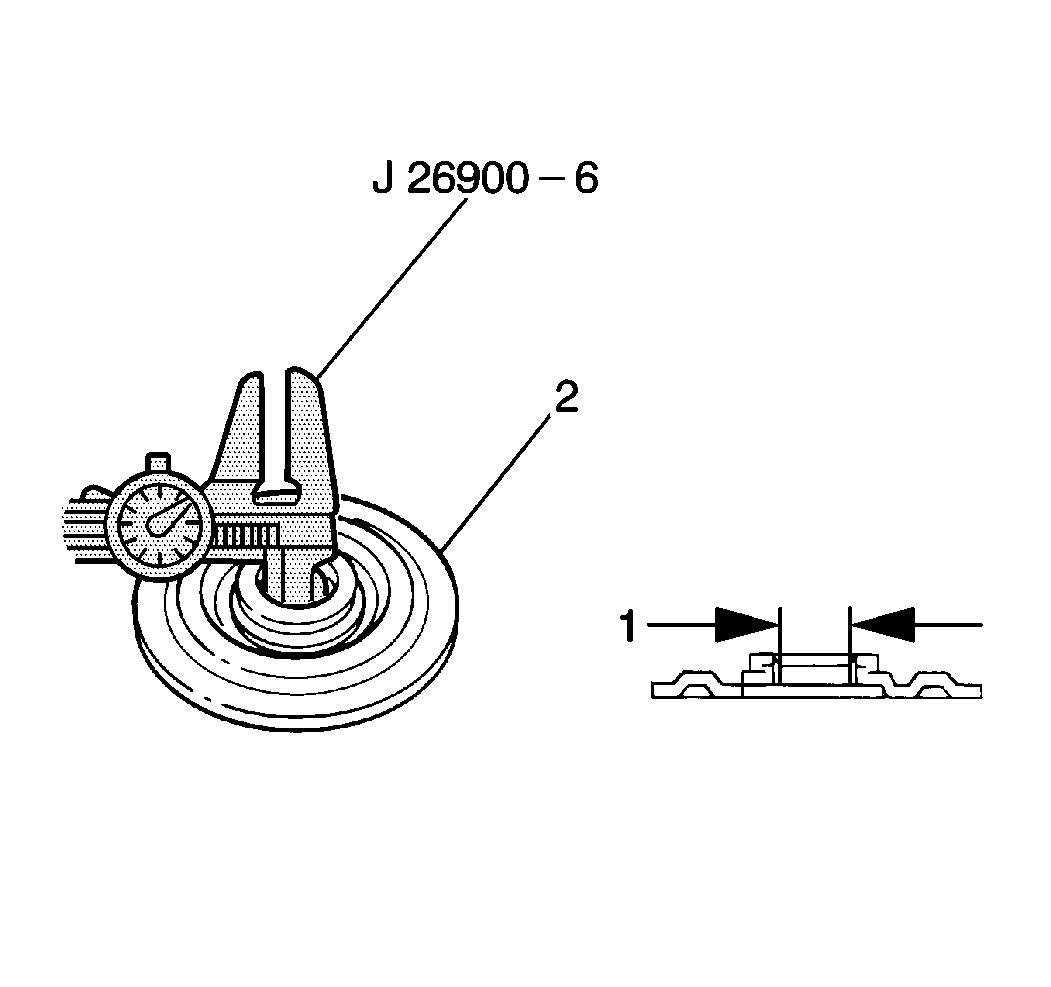
| • | The standard front planetary ring gear flange bushing inside diameter should fall within 19.025 - 19.050 mm (0.7490 - 0.7500 in). |
| • | If the front planetary ring gear flange bushing inside diameter is greater than 19.050 mm (0.7500 in), replace the front planetary ring gear flange. |
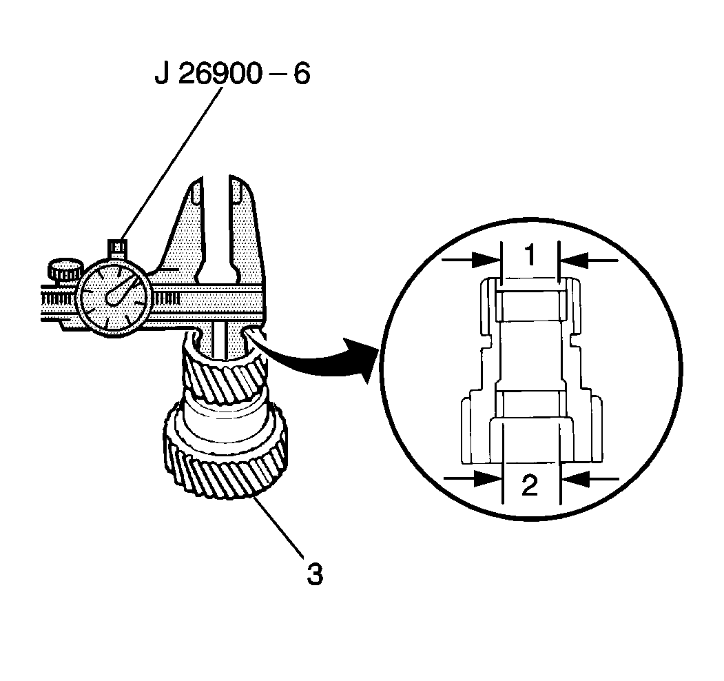
| • | The standard sun gear flange bushing inside diameter (1) should fall within 22.025 - 22.046 mm (0.8671 - 0.8680 in). |
| • | The maximum sun gear flange bushing inside diameter (2) is 22.096 mm (0.8699 in). |
| • | If the sun gear flange bushing inside diameter is greater than specified, replace the sun gear. |
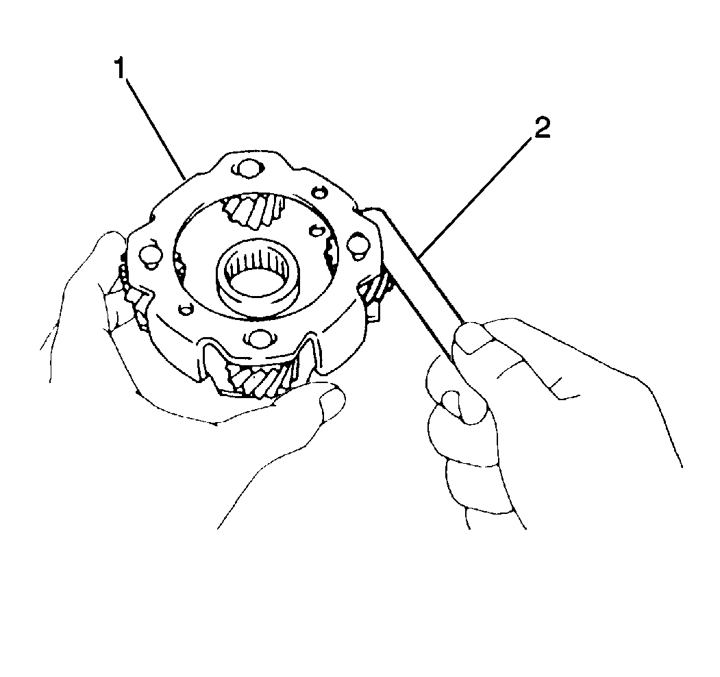
| • | The standard front planetary carrier pinion gear thrust clearance should fall within 0.20 - 0.50 mm (0.008 - 0.020 in). |
| • | If the front planetary carrier pinion gear thrust clearance is greater than 0.50 mm (0.020 in), replace the front planetary carrier. |
Installation Procedure
- Install the sun gear snap ring onto the sun gear.
- Install the sun gear into the sun gear input drum.
- Install the sun gear input drum snap ring onto the sun gear at the rear of the sun gear input drum.
- Install the front planetary ring gear flange into the front planetary ring gear; secure with the front planetary ring gear flange snap ring.
- Install the intermediate one-way clutch sprag assembly and retainers into the intermediate brake hub.
- Install the rear thrust plate onto the intermediate brake hub.
- Inspect the intermediate one-way clutch after assembly by placing the intermediate brake hub and intermediate one-way clutch onto the rear of the sun gear input drum, holding the sun gear input drum stationary and rotating the intermediate brake hub.

| • | The intermediate brake hub should turn freely in a clockwise direction (2) and should not turn in a counterclockwise direction (4). |
| • | If the intermediate brake hub is installed correctly on the sun gear input drum and the intermediate brake hub can be turned counterclockwise, replace the intermediate brake hub and the intermediate one-way clutch. |
